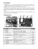
background image

4


Operation 


Getting Started 


It  is  necessary  to  first  fully  charge  the  Battery  Pack  as  described  below  and  to  have  a  few 
electronic  identification  ear  tags  or  implants  available  for  testing. 

It  is  very  important  to 

carry out the three steps described in this section before using the reader (see “Battery 
handling instructions” section for more information) 


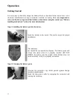
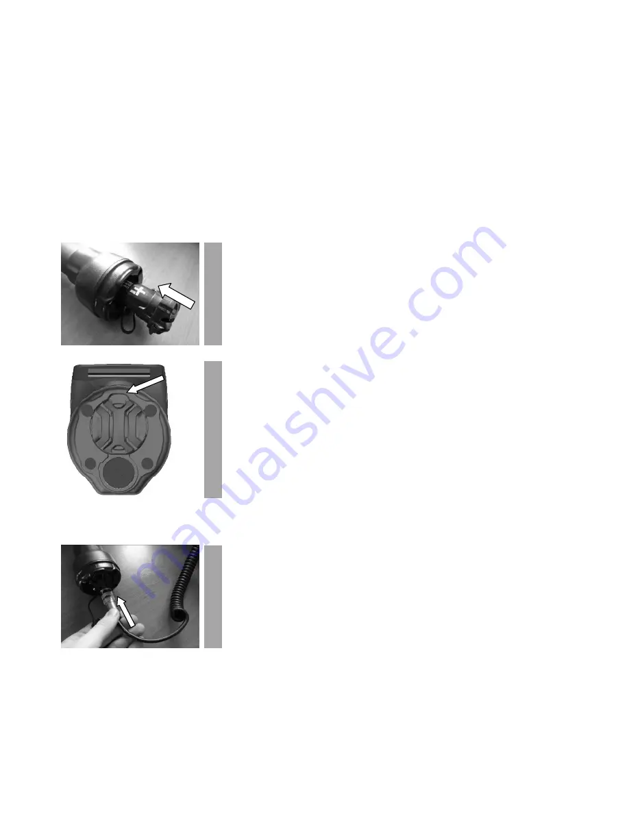
Step 1: Installing the battery pack in the device. 


Insert  the  battery  in  the  reader.  The  pack  is  keyed  for  proper 
installation. 


The stationary  
key  should  be  up  towards  the  display.  The  battery  pack  will 
“snap”  into  place  when  it  is  properly  inserted.  DO  NOT 
FORCE  the  battery  into  the  reader.  If  the  battery  does  not 
insert smoothly, verify it is properly orientated. 


Step 2: Charging the battery pack. 


Unscrew  the  protective  cap  which  guards  against  foreign 
material contamination. 
Insert  the  data-power  cable  by  engaging  the  connector  and 
rotating the lock-ring. 


Summary of Contents for RS420

Page 1: ...RS420 Portable stick reader USER MANUAL Version 1 0 ...

Page 2: ...5 2 Reader 3 IEC cable Supply cable to power the external adapter 4 CD ROM Support for user manual and reader datasheets E88VE018 5 Data Power Cable Conveys external power to reader and serial data to and from reader E88VE017 6 External Power Adapter Powers the reader and charges the battery E88VE020 7 USB flash drive adapter Allows the user to connect an USB stick to upload or to download data to...

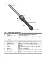
Page 3: ...reen indicator Illuminates whenever a transponder data has been stored 6 Red indicator Illuminates whenever antenna is emitting activation signal 7 black MENU button Navigates in the reader menu to manage or to configure it 8 green READ button Applies power and causes activation signal to be emitted for reading transponder 9 Vibrator Vibrates once on first transponder reading and short vibrates fo...

Page 4: ...tep 1 Installing the battery pack in the device 1 Insert the battery in the reader The pack is keyed for proper installation 2 The stationary key should be up towards the display The battery pack will snap into place when it is properly inserted DO NOT FORCE the battery into the reader If the battery does not insert smoothly verify it is properly orientated Step 2 Charging the battery pack 1 Unscr...

Page 5: ...in the reader Power on instructions Press the green button on the reader handle to power on the reader The main screen will appear on the display Item Feature Description of use 1 Battery level The battery level shows the fully charged level as well as the charge level during the charge mode 2 USB connection Appears when the reader is connected to a computer via USB port NOTE The reading mode is d...

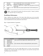
Page 6: ... the reader within which tags can be successfully detected and read Optimum read distance occurs depending upon the orientation of the tag Tags and implant read best when positioned as shown below Figure 2 Optimum Read Distance Tag Orientation Item Legend Comments 1 Reading zone Area in which the ear tags and the implants can be read 2 RFID Ear tag 3 RFID Implant 4 Best orientation Best orientatio...

Page 7: ...the reading mode remains indefinitely activated until you press the green button a second time The following picture shows the result of a successful reading session Item Feature Description of use 1 Transponder type ISO standard 11784 5 has approved 2 technologies for animal identification FDX B and HDX When the reader displays the word IND as transponder type it means that its transponder is not...

Page 8: ... different read range performance levels 3 Animal movement If the animal moves too quickly the transponder may not be located in the read zone long enough for the ID code information to be obtained 4 Transponder type HDX and FDX B transponders generally have similar reading distances but tag manufacturers and environmental factors such as RF interferences may affect overall tag performances 5 Near...

Page 9: ...ure cannot directly be connected to other transceivers To prevent a mobile transceiver interfering with the interrogation protocol of other transceivers it must be able to detect the presence of additional active transceivers through the reception of activation signals If no activation signal is detected within 30 ms the transceiver is out of reach of other active transceivers and its activation s...

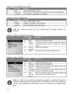
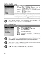
Page 10: ...omatically closes the menu if no action occurs for 8 seconds Session management Menu 2 Menu session Item Sub Menu Definition 1 Back Return to the previous screen 2 New working session Create a new work session after validation by the user This new session becomes the current one and the previous one is closed 3 Open working session List all stored sessions and indicates the number of existing save...

Page 11: ... Back Return to the previous screen 2 Bluetooth Send session s via the Bluetooth link 3 USB flash drive Store the session s on flash drive memory stick see Note 9 4 USB link Send session s via the USB link 5 Serial link Send session s via the Serial link Note 8 Connect your flash drive memory stick establish an USB connection a serial connection or a Bluetooth connection before to select the sessi...

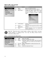
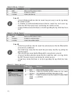
Page 12: ...e by iPhone iPad and iPod 6 About Provide information about the Bluetooth features see Menu 7 Note 10 When the reader is discoverable by iPhone iPad or iPod a message pairing finished is displayed Press Yes once the iPhone iPad or iPod is connected via Bluetooth Menu 7 Information about Bluetooth Item Feature Description of use 1 Name Name of the reader 2 Addr Address of the Bluetooth module 3 Pai...

Page 13: ...mode Manage the storage of read tag no storage on read and on read but no duplicated in the memory 4 Comparison and Alerts Manage comparison and alerts regarding read tags see Menu 12 5 Counter mode Manage the counters displayed on main screen 6 RFID Power Mode Manage the power consumption of the device see Menu 10 7 Temperature Manage the temperature detection This option is useful with Bio Therm...

Page 14: ...ader and select the comparison session used to compare the read ID codes 3 Disable compare Disable the comparison 4 Alerts Enter into the menu alerts see Menu 13 Menu 13 Menu Alerts Item Sub Menu Definition 1 Back Return to the previous screen 2 Disabled Disable the alert management 3 On animal found Produce an alert signal when the read ID code is found in the comparison session 4 On animal not f...

Page 15: ...sponds to the current settings of the reader which can be dedicated to a custom use The user can save up to 4 profiles Menu 15 Menu quick action Item Sub Menu Definition 1 Back Return to the previous screen 2 Disabled No feature attributed to the black button 3 Enter menu Fast access to the menu 4 New session Fast creation of a new session 5 Re send last tag Last read tag is re sent on the communi...

Page 16: ... 3 Enabled Enable the audible beeper Note 20 A short beep indicates that the reader has switched on or that the Bluetooth connection is established Two short beeps mean that the reader has previously read the tag during the current session Three short beeps mean that the Bluetooth connection is removed A beep of medium duration means that the reader has read a new tag which has NOT been previously...

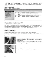
Page 17: ...a PC This section is meant to describe how to connect the reader to hand held computer PDA or to a personal computer PC The device can be connected to a PC in 3 ways a wired USB connection a wired RS 232 connection or by a wireless Bluetooth connection Using USB interface The USB port allows the device to send and receive data via a USB connection To establish a USB connection simply connect the r...

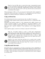
Page 18: ... no parity 8 bits 1 word and 1 stop bit 9600N81 These parameters can be changed from PC software Serial output data appears on the device s TxD pin 2 connection in ASCII format Note 23 The RS232 interface is wired as a DCE data communications equipment type that connects directly to the serial port of a PC or any other device that is designated as a DTE data terminal equipment type When the device...

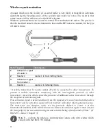
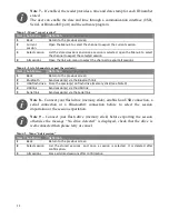
Page 19: ... MASTER the icon is In both cases the icon stops to blink If you are using a PDA it will require software Not supplied by the manufacturer Your software supplier will explain how to connect the PDA Note 25 We advise that to achieve successful Bluetooth connection with your reader simply follow the implementation methods listed see the following Note 26 If these implementation methods are not follo...

Page 20: ...dertaken On the reader go to the menu Bluetooth and then select slave in the sub menu select device to remove the previous pairing and allow the reader to return to SLAVE mode Start your PC Bluetooth Manager program or PDA Bluetooth services Depending on which Bluetooth device your PC is using the Bluetooth Manager may vary in how it pairs a device As a general rule the program should have the opt...

Page 21: ...red to connect the reader to the PC PDA In such case the PIN code to use is 1234 Reader to a Bluetooth adapter connected to a scale head or to a Bluetooth enabled device such as scale head or printer This scenario requires that the reader lists the Bluetooth peripherals Go to the menu Bluetooth then the sub menu Search device which launches the Bluetooth scanning The device you want to connect to ...

Page 22: ...1 From its AC Adapter Once the external AC adapter is connected the reader is powered up it will remain on until the AC adapter is disconnected and the Battery Pack is charged The reader can be powered regardless of the charge state of the Battery Pack The AC Adapter can be used as a power source even if the Battery Pack has been removed from the device If the AC Adapter has been connected the use...

Page 23: ...gainst foreign material contamination Install the data power cable by engaging the connector and rotating the lock ring 2 Then connect the other end of the battery cable into the power socket located at the end of the reader s data power cable Step 3 Checking the reader 1 Once you are connected to a power source the reader display s backlight will turn on Press the green button momentarily and not...

Page 24: ...N IF BATTERY IS REPLACED BY AN INCORRECT TYPE DISPOSE OF USED BATTERIES ACCORDING TO THE INSTRUCTIONS Note 31 Do not use this reader near water when connected to the AC DC adapter Note 32 Do not install near any heat sources such as radiators heat registers stoves or other apparatus that produce heat Note 33 Do not charge the battery pack from AC main sources during electrical storms or when unuse...

Page 25: ...posal Warning 1 Do not immerse the battery in water 2 Keep the battery in a cool dry environment during storage periods 3 Do not use or leave the battery near a heat source such as fire or heater 4 When recharging use only the battery charger from manufacturer 5 The battery charge should be realized at a temperature between 0 and 45 C 6 Do not let the battery terminals and contact any metal like a...

Page 26: ...tery charging Green light Red light Charger status Off Off Not Charging Standby or Shutdown Off On Bad Battery fault On Off Normal Charging On On Temperature fault Note 35 The lights switch off when the batteries are fully charged The battery charger can be placed horizontally or vertically on a table Make sure the battery orientation is correct before insertion into the charger ...

Page 27: ...27 Plastic Carry Case Durable Plastic Carry Case is available as an optional extra or is included in the Premium Kit Package ...

Page 28: ...ble Date Time autonomy 3 monthswithout reader usage 20 C Battery charge duration 3 hours Mechanical and physical Dimensions Long reader 670 x 60 x 70 mm 26 4 x 2 4 x 2 8 in Short reader 530 x 60 x 70 mm 20 9 x 2 4 x 2 8 in Weight Long reader with battery 830 g 29 3 oz Short reader with battery 810 g 28 6 oz Material ABS PC and fiberglass tube Operating temperature 20 C to 55 C 4 F to 131 F Storage...

Page 29: ...aterials or workmanship for a period of one year following the date of purchase The warranty does not apply to any damage resulting from an accident misuse modification or an application other than that described in this manual and for which the device was designed If the product develops a malfunction during the warranty period manufacturer will repair or replace it free of charge The cost of shi...

Page 30: ...relocate the receiving antenna Increase the distance between the equipment and the receiver Connect the equipment to outlet on a circuit different from that to which the receiver is connected Consult the dealer or an experienced radio TV technician for help The user must be at 20 cm of the reader antennas Notice to Consumers Any changes or modifications not expressly approved by the party responsi...

Page 31: ...ational Standardization Organization Specifically with standards 11784 Radio frequency identification of animals Code Structure 11785 Radio frequency identification of animals Technical Concept FCC NQY 30002 IC 4246A 30002 CE Marking Trademark Notices Bluetooth is a registered trademark of Bluetooth SIG Inc ...

Page 32: ...ca 8300 Distrito Industrial Bloco B Módulos 7 e 8 89 239 270 JOINVILLE SC BRASIL Tel 55 47 451 05 00 ALLFLEX ARGENTINA CUIT N 30 70049927 4 Pte Luis Saenz Peña 2002 1135 CONSTITUCIÓN CABA BUENOS AIRES ARGENTINA Tel 54 11 41 16 48 61 BEIJING ALLFLEX PLASTIC PRODUCTS SAN TAI SHAN XIAO HONG MEN CHAO YANG DISTRICT PO BOX 5206 BEIJING CHINA Tel 86 10 87606130 Allflex Australia 33 35 Neumann Road Capala...

Reviews: