Allen-Bradley ArmorBlock 1732D A Series Installation Instructions Manual Download Page 1

1

Publication 1732D-IN001B-EN-E - May 2004

Installation Instructions

DeviceNet 1732 ArmorBlock I/O, Series A

(Cat. Nos. 1732D-IB8M12, -IB8M8, -OB8EM12, -OB8EM8, 
-8CFGM12, -8CFGM8)

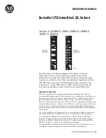
The DeviceNet 1732D ArmorBlock™ I/O family consists of 
stand-alone 24V dc I/O modules that communicate via the 
DeviceNet

 network. The sealed IP67 housing of these modules 

requires no enclosure (Note that environmental requirements other 
than IP67 may require an additional appropriate enclosure.) I/O 
connectors are sealed M8 (pico) or M12 (micro) styles while the 
network and auxiliary power connectors are sealed M12 style. 

Important User Information

Solid state equipment has operational characteristics differing from those of 
electromechanical equipment. 

Safety Guidelines for the Application, Installation and 

Maintenance of Solid State Controls

 (Publication SGI-1.1 available from your local 

Rockwell Automation sales office or online at http://www.ab.com/manuals/gi) 
describes some important differences between solid state equipment and hard-wired 
electromechanical devices. Because of this difference, and also because of the wide 
variety of uses for solid state equipment, all persons responsible for applying this 
equipment must satisfy themselves that each intended application of this equipment 
is acceptable.

In no event will Rockwell Automation, Inc. be responsible or liable for indirect or 
consequential damages resulting from the use or application of this equipment.

The examples and diagrams in this manual are included solely for illustrative 
purposes. Because of the many variables and requirements associated with any 
particular installation, Rockwell Automation, Inc. cannot assume responsibility or 
liability for actual use based on the examples and diagrams.

No patent liability is assumed by Rockwell Automation, Inc. with respect to use of 
information, circuits, equipment, or software described in this manual.

31433-M

M12 Style 
Connectors

M8 Style 
Connectors

Summary of Contents for ArmorBlock 1732D A Series

Page 1: ...Automation sales office or online at http www ab com manuals gi describes some important differences between solid state equipment and hard wired electromechanical devices Because of this difference and also because of the wide variety of uses for solid state equipment all persons responsible for applying this equipment must satisfy themselves that each intended application of this equipment is ac...

Page 2: ...ons as defined in IEC publication 60664 1 at altitudes up to 2000 meters without derating This equipment is considered Group 1 Class A industrial equipment according to IEC CISPR Publication 11 Without appropriate precautions there may be potential difficulties ensuring electromagnetic compatibility in other environments due to conducted as well as radiated disturbance This equipment is supplied a...

Page 3: ...e switches The two switches are X10 most significant digit left side of module X1 least significant digit right side of module To reset the node address use a small blade screwdriver to rotate the switches Line up the small black dot on the switch with the number setting you wish to use and then cycle power ATTENTION Preventing Electrostatic Discharge This equipment is sensitive to electrostatic d...

Page 4: ...ing red MOD LED Settings between 64 and 99 cause the module to use the last valid node address stored internally Example The last setting internally was 40 If a change is made to 68 and then you power up the address will default to 40 The module is equipped with AutoBaud detect AutoBaud lets the module read the settings already in use on your DeviceNet network and automatically adjusts to follow t...

Page 5: ...t are used to mount the module directly to a panel or machine The module can be front or side mounted Mounting holes accommodate 6 M3 pan head screws The torque specification is 6 in lbs 1 46in 37mm 67in 17mm 78in 19 8 mm 6 56in 166 5mm 6 64in 168 6mm 7 05in 179mm 1 06in 27mm 1 70in 43 3mm 1 26 in 32mm 9577597 101 Front Mounting Side Mounting ...

Page 6: ... Mount the flat and lock washer as shown in the following illustration Torque the mounting screws to 6 in lbs Connect the Input Output Cord Sets to the ArmorBlock Module The ArmorBlock family offers 5 pin micro style PCB mounting connectors or 3 pin pico style PCB mounting connectors We provide caps to cover the unused connectors on your module Connect the quick disconnect cord sets you selected f...

Page 7: ...Input A Pin 5 Not used Output Connector Cat Nos 1732D OB8EM12 view into connector Pin 1 Not Used Pin 2 Output B Pin 3 Return Pin 4 Output A Pin 5 Not Used 5 Pin Micro Style 12mm Female Connectors Input Connector Cat Nos 1732D IB8M8 view into connector Pin 1 Sensor Source voltage Pin 3 Return Pin 4 Input Output Connector Cat Nos 1732D OB8EM8 view into connector Pin 1 Not Used Pin 3 Return Pin 4 Out...

Page 8: ... reference the 889P products IMPORTANT If the devices sensors connected to the input connections require Class 2 power to operate the auxiliary power connections of this equipment must be powered by a Class 2 source ATTENTION Make sure all connectors and caps are securely tightened to properly seal the connections against leaks and maintain IP67 requirements MSD LSD DeviceNet Node Address 4 12mm o...

Page 9: ...tivation deactivation of sensors and actuators always wire input sensors and output actuators directly to the I O connectors Communicate With Your ArmorBlock I O Module This ArmorBlock module s I O is exchanged with the master through a poll change of state or cyclic connection Cyclic allows configuration of the block as an I O client The block will produce and consume its I O cyclically at the ra...

Page 10: ...be an output dedicate that point as an output with a wired load and energize it through a control program If an I O point is to be an input wire the input device as normal and leave the associated output un energized at all times 1732D IB8M12 and 1732D IB8M8 1732D OB8EM8 and 1732D OB8EM12 The DeviceNet Network uses advanced network technology producer consumer communication to increase network fun...

Page 11: ...rs Network and Module status indicator for DeviceNet Auxiliary Power indicator Individual I O status indicators for inputs and outputs I O Status Indicators M8 Style Connectors Module Indicator Network Indicator Auxiliary Power Indicator 43820 M12 Style Connectors I O Status Indicators Module Indicator Network Indicator Auxiliary Power Indicator 43821 ...

Page 12: ...he established state The device has passed the dup_MAC_id test is on line but has no established connections to other nodes As a Group 2 device it means that the device is not allocated to a master Critical link failure Solid Red Failed communication device The device has detected an error that has rendered it incapable of communication on the network dup_MAC_id failure or bus off Connection time ...

Page 13: ...icators Function Point Indicator Condition Outputs None Yellow Output not energized Output energized Inputs None Yellow No valid input Valid input DeviceNet 1732 ArmorBlock I O Series A Input Specifications Inputs 61131 2 Type 3 Compatible Sensor Source Current Maximum per input 50mA Sensor Source Current Maximum per module 400mA Sensor Source Voltage auxiliary power 12 30V dc Maximum Minimum 30V ...

Page 14: ...g Thermal Shock 20 to 60 C 4 to 140 F Storage Temperature IEC 60068 2 1 Test Ab Un packaged Non operating Cold IEC 60068 2 2 Test Bb Un packaged Non operating Dry Heat IEC 60068 2 14 Test Na Un packaged Non operating Thermal Shock 45 to 85 C 49 to 185 F Relative Humidity IEC 60068 2 30 Test Db Un packaged Non operating Damp Heat 5 95 non condensing Shock IEC60068 2 27 Test Ea Unpackaged Shock Oper...

Page 15: ...unity EN 61326 Meas Control Lab Industrial Requirements EN 61000 6 2 Industrial Immunity C Tick3 Australian Radiocommunications Act compliant with AS NZS CISPR 11 Industrial Emissions ODVA ODVA conformance tested to DeviceNet specifications 1 You use this conductor category information for planning conductor routing as described in the system level installation manual 2 See pub 1770 4 1 Programmab...

Page 16: ...ce a problem with a hardware module within the first 24 hours of installation please review the information that s contained in this manual You can also contact a special Customer Support number for initial help in getting your module up and running New Product Satisfaction Return Rockwell tests all of our products to ensure that they are fully operational when shipped from the manufacturing facil...

Reviews: