Allen-Bradley 6177R Installation Instructions Manual Download Page 4

4

Rockwell Automation Publication IC-IN001A-EN-P - July 2017

Microsoft Windows 10 IoT Enterprise LTSB Operating System Upgrade Kit

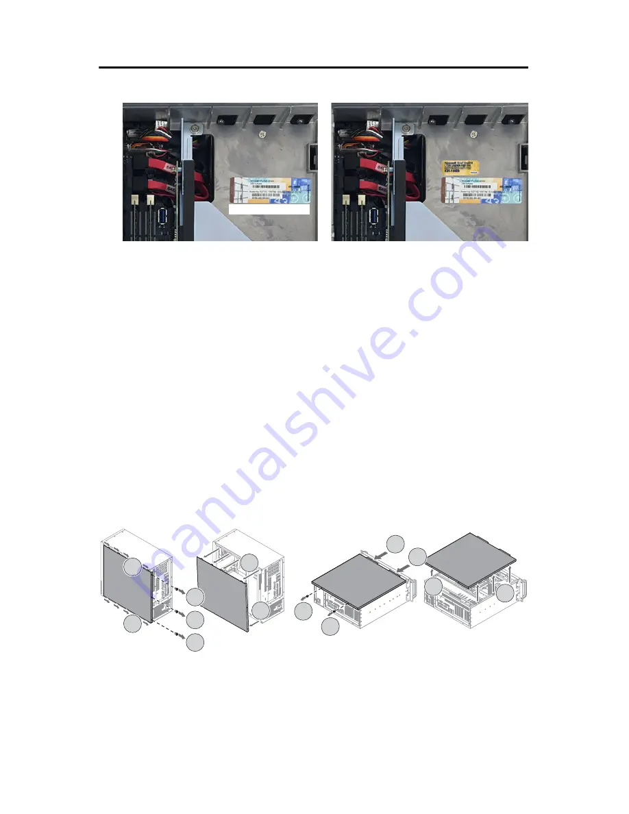
4. Place the new Windows 10 COA label near (but not over) the existing COA label.

5. If necessary, reinstall the add-in card.

6. Reattach the rear cover to the computer chassis.

7. Close the cover.

8. Tighten the three captive screws to secure the rear cover.

9. Restore power to the computer.

For 6177R Series C Computers (750R and 1450R models)

1. Remove power from the computer.

2. Unfasten the cover from the computer chassis.

• 750R computers: Remove the three screws on the rear edge of the side cover (A).

• 1450R computers: Remove the two screws on the rear edge of the top cover (A).

3. Slide the cover back about 1.5 cm (0.5 in.) to release the hinge tabs (B).

4. Tilt the cover up slightly to disengage the hinge tabs from their lock slots.

5. Pull the cover away from the chassis (C).

6. Locate the existing COA label.

• 750R computers: The label is underneath the top cover.

• 1450R computers: The label is on a side cover.

Existing

750R Computer

1450R Computer

A

A

A

C

B

C

B

A

B

C

B

C

A

Summary of Contents for 6177R

Page 1: ...to download and upgrade to the Microsoft Windows 10 IoT Enterprise Long Term Service Branch LTSB operating system OS Topic Page Install the Two Labels 2 Download and Install the Windows 10 IoT Enterpr...

Page 2: ...led envelope To install the two replacement labels perform the following steps RockwellAutomationWindows10UpgradeLabel For6181PSeriesFComputers 1 Locate the barcode label on the side of the computer 2...

Page 3: ...tach it from the chassis The existing COA label is on the back panel of the chassis IMPORTANT If an add in card is installed you might need to remove the card to access the COA label Add incards are s...

Page 4: ...750Rand1450Rmodels 1 Remove power from the computer 2 Unfasten the cover from the computer chassis 750R computers Remove the three screws on the rear edge of the side cover A 1450R computers Remove th...

Page 5: ...steps 1 Attach the following external peripherals to your computer Display for non display models Keyboard and mouse USB FAT32 storage drive 16 GB or larger 2 Access the Rockwell Automation Product Co...

Page 6: ...r model In nearly all instances the AMI Rescue file should be selected 8 Click Downloads 9 On the Download Cart dialog box click Download Now 10 Download the system image to the root of the attached U...

Page 7: ...wnloaded open the USB drive 13 In the USB drive directory double click to launch the extraction process 14 On the extraction dialog box perform the following a Verify that the USB drive is the destina...

Page 8: ...ce 4 From the List of Volumes menu select the USB storage drive 5 Click Exit 6 In the Destination of Restore Data field click Browse to locate the destination source 7 Select the volume label for the...

Page 9: ...AMI Restore 3 Select the appropriate volume from the list Recovery is the volume name where the default backup of factory images is stored 4 Click Next IMPORTANT Ifwarningmessagesappearduringtheresto...

Page 10: ...estore 6 Click Advanced 7 Select to which disk partition you want to restore 8 Click OK 9 Click Restore to start the restoration process The restoration process starts TIP All checkboxes must be selec...

Page 11: ...Allen Bradley distributor or Rockwell Automation sales representative Resource Description RockwellAutomationPCDCQuickReferenceGuide publication PCDC QR001 Provides an overview of the Rockwell Automat...

Page 12: ...he HowAre We Doing form at http literature rockwellautomation com idc groups literature documents du ra du002_ en e pdf RockwellAutomationSupport Use the following resources to access support informat...

Reviews: