background image

Rockwell Automation Publication 6176M-UM001D-EN-P - December 2012

21

Installation

Chapter 2

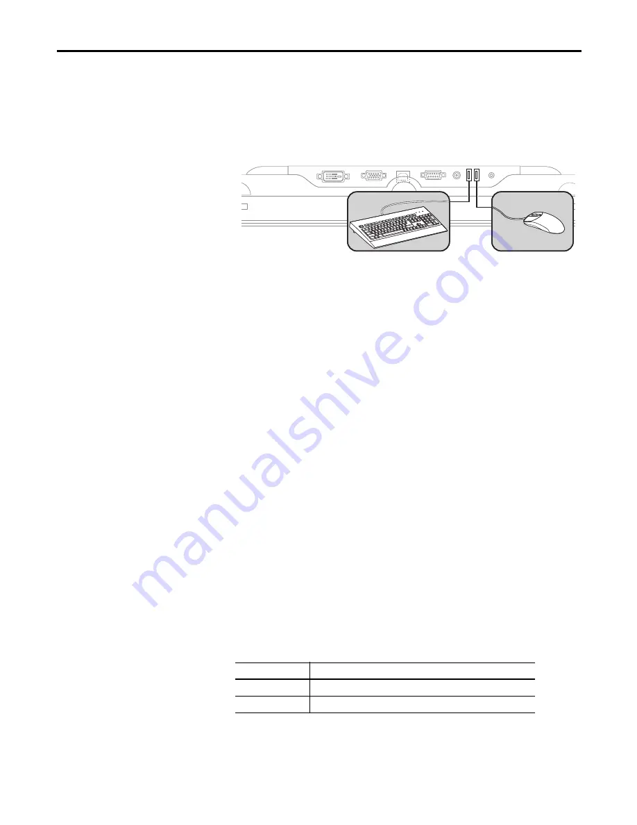
Connect USB Peripheral Devices

The monitor is equipped with a USB hub that provides communication between 
a computer and any USB compatible device, such as a keyboard, mouse, or 
memory stick. The USB hub ports are enabled only when the monitor is powered 
on and the connection is made between the type B connector and the computer.

Connect the Optional Touchscreen Interface

An optional touchscreen provides a high-resolution touch input system. The 
driver software included with the monitor lets the touchscreen function with 
many Microsoft Windows industrial applications such as a pointing device or 
mouse.

A touchscreen interface to the computer can be configured using either the serial 
RS-232 connection or USB connection.

Connect the Optional Serial RS-232 Touchscreen Interface

The RS-232 DB9 (female) D-shell connector on the bottom side of the monitor 
provides the serial touchscreen interface connection to the host.

Follow these directions to connect the touchscreen interface.

1.

For units with the touchscreen option, connect one end of the included 
touchscreen serial cable to the RS-232 port connector on the monitor. 

2.

Connect the other end of the cable to a serial port on the host computer.

3.

Tighten the captive screws on the cable connector to secure it.

Connect the USB and Optional USB Touchscreen Interface

The USB Type A connection to the host computer is used to connect USB 
devices and the optional USB touchscreen interface to the host computer.

Cat. No.

Description

6189V-TCHCBL2

Serial touch cable, RS-232 cable, 1.8 m (6 ft)

6189V-USBCBL2

USB/USB touch cable, Type A to Type B, 1.8 m (6 ft)

Summary of Contents for 6176M-15PN

Page 1: ...Standard Industrial Monitors Catalog Numbers 6176M 15VN 6176M 15VT 6176M 15PN 6176M 15PT 6176M 17VN 6176M 17VT 6176M 17PN 6176M 17PT 6176M 19VN 6176M 19VT 6176M 19PN 6176M 19PT User Manual...

Page 2: ...ility is assumed by Rockwell Automation Inc with respect to use of information circuits equipment or software described in this manual Reproduction of the contents of this manual in whole or in part w...

Page 3: ...oved rack mounting information for 1550M and 1750M monitors 17 Added step 2 and illustration to Mounting the Monitor on a Bench or Tabletop subsection 19 Modified illustration in Monitor Connections s...

Page 4: ...4 Rockwell Automation Publication 6176M UM001D EN P December 2012 Summary of Changes Notes...

Page 5: ...learance Requirements 14 Monitor Dimensions 15 Install the Monitor 15 Panel Mounting 15 Rack Mounting 1950M monitors 17 VESA Mounting 18 Monitor Connections 19 Connect to an Analog Video Source 20 Con...

Page 6: ...5 Replace a Line Cord 35 Other Maintenance 36 Backlight Assembly Disposal 36 Ship or Transport the Monitor 36 Chapter5 TroubleshoottheMonitor Chapter Objective 37 Run the Self test 37 Troubleshooting...

Page 7: ...utomation com literature To order paper copies of technical documentation contact your local Allen Bradley distributor or Rockwell Automation sales representative Abbr Meaning Abbr Meaning BIOS Basic...

Page 8: ...8 Rockwell Automation Publication 6176M UM001D EN P December 2012 Preface Notes...

Page 9: ...e a visualization maintenance control or information computing solution Standard industrial monitors offer the following features 15 17 and 19 inch displays VESA and panel mount options Active matrix...

Page 10: ...and Accessories CD that contains device drivers Installation instructions this document Cutout template publication 6186M DS001 Mounting clips Four VESA mounting screws M4 x 0 7 Power adapter and line...

Page 11: ...edures to mount the monitor and make connections The chapter covers the following topics Installation Precautions Installation Guidelines Required Tools Mounting Clearance Requirements Monitor Dimensi...

Page 12: ...ulting from accessibility to live parts UL Listed equipment need not be mounted inside another enclosure in ordinary nonhazardous locations if NEMA Type and IEC ratings are not required but the mounti...

Page 13: ...ipment through the AC power cord helps to reduce static discharges which may cause shocks and damage electronic components The enclosure or cover must remain in place at all times during operation The...

Page 14: ...ce around the monitor for ventilation and cable connections IMPORTANT Do not operate the monitor in an enclosure that uses minimum clearances unless adequate ventilation or other cooling methods are u...

Page 15: ...6176M Model Mount A height B width C depth Panel Cutout Height Panel Cutout Width 1550M Panel 309 mm 12 3 in 410 mm 16 1 in 50 mm 2 0 in 285 6 mm 11 24 in 386 6 mm 15 22 in VESA 282 6 mm 11 0 in 383 6...

Page 16: ...ounttheMonitorinaPanel Follow these steps to mount the monitor in a panel 1 Cut the panel opening using the appropriate cutout dimensions 2 Attach cables to the monitor before installing if rear acces...

Page 17: ...s on page 16 Mountthe1950MMonitorinaRack Follow these steps to mount the 1950M monitor in an EIA rack cabinet 1 Position the monitor into a standard 19 inch EIA rack cabinet A as shown in Figure 2 on...

Page 18: ...MI 100 mm 3 94 in standards The mounting location must provide adequate clearance for positioning and moving the adjustable unit and for routing cables ATTENTION The mounting rails that run vertically...

Page 19: ...the arm Monitor Connections Use the connectors on the rear of the monitor to connect the following Analog video source HD 15 VGA connector Digital video source DVI connector Serial port on a computer...

Page 20: ...digital video cable to the female DVI video input connector on the monitor 2 Connect the other cable end to the output of any digital DVI video source Cat No Description 6189V VGACBL2 Analog video cab...

Page 21: ...be configured using either the serial RS 232 connection or USB connection ConnecttheOptionalSerialRS 232TouchscreenInterface The RS 232 DB9 female D shell connector on the bottom side of the monitor...

Page 22: ...found on the Accessories CD or at http www ab com linked industrialcomputers drivers monitors html PerformaCalibration After installing the driver follow the calibration instructions in the touchscre...

Page 23: ...input connector on the monitor A 2 Secure this connection by screwing the barrel over the threads B 3 Connect the AC power cord to the main power supply C Functional Ground Screw Using the functional...

Page 24: ...24 Rockwell Automation Publication 6176M UM001D EN P December 2012 Chapter 2 Installation Notes...

Page 25: ...tion Flat panel monitors are fixed resolution devices The image looks best when the monitors are operated at their native resolution However the monitors have advanced scaling capabilities to make the...

Page 26: ...or at least three seconds Adjust the Monitor Brightness To adjust brightness levels use the Adjust buttons on the rear of the monitor Press the button to increase brightness and the button to decrease...

Page 27: ...lity that is named ScreenSet exe 3 Press the Auto Adjust Exit button The auto adjustment display appears Your screen has the potential to flicker during the Auto Setup process When the auto adjustment...

Page 28: ...of the six OSD main menu tabs starting on page 30 for where the Back and Exit buttons are located Press the Menu Return button to do the following Open the OSD main menu Activate the highlighted func...

Page 29: ...s on the signal from the computer and the type of cable connected to the monitor Brightness Contrast Accesses functions to adjust the brightness and contrast Color Accesses functions to select standar...

Page 30: ...signal from the 15 pin VGA input connector DVI digital input Displays the incoming DVI digital signal from the DVI input connector Back Returns to the OSD main menu Icon Function Value Range Brightnes...

Page 31: ...screen 0 100 sRGB Automatically adjusts the RGB settings Temperature Adjusts the color temperature values Back Returns to the OSD main menu Temperature Functions Description Value Range Temperature S...

Page 32: ...mage position frequency phase and blacklevel Width Adjusts the width 0 100 Phase Adjusts the sampling phase 0 100 Horizontal Position Adjusts the horizontal position of the image on the screen 0 100 V...

Page 33: ...ets all OSD settings to factory defaults Horizontal Position Adjusts the horizontal position of the OSD menu 0 255 Back Returns to the OSD main menu Vertical Position Adjusts the vertical position of...

Page 34: ...34 Rockwell Automation Publication 6176M UM001D EN P December 2012 Chapter 3 Display Configuration Notes...

Page 35: ...touch screen shield that is installed over the screen Abrasive and certain chemical cleaners can easily damage the surface Replace a Line Cord To avoid shock and fire hazards replace the monitor s po...

Page 36: ...n you must first uninstall the monitor and place it in its original packing material ATTENTION The backlight assembly in this monitor contains mercury At the end of its life this monitor must be colle...

Page 37: ...teps to run the self test 1 Shut down the computer and disconnect power to the monitor 2 Unplug the video cable from the back of the computer 3 Apply power to the monitor If the monitor is functioning...

Page 38: ...e using the video cable supplied with the monitor or a similar high quality cable Perform a monitor reset Eliminate unnecessary accessories such as video extension cables Perform the automatic video a...

Page 39: ...Colors are distorted with dark or shadowed areas Adjust the color setting using the appropriate OSD menu White does not look white Adjust the color setting using the appropriate OSD menu Image positio...

Page 40: ...40 Rockwell Automation Publication 6176M UM001D EN P December 2012 Chapter 5 Troubleshoot the Monitor Notes...

Page 41: ...play area WxH approx 305 x 229 mm 9 0 x 12 0 in 338 x 270 mm 13 3 x 10 7 in 377 x 302 mm 14 8 x 11 9 in Resolution WxH approx 1024 x 768 native mode 16 7M colors 1280 x 1024 native mode 16 7M colors L...

Page 42: ...F Relative humidity 10 90 noncondensing Shock Operating Nonoperating 15 g 1 2 sine 11 ms 20 g 1 2 sine 11 ms Shock Operating Nonoperating 15 g 1 2 sine 11 ms 20 g 1 2 sine 11 ms Vibration Operating N...

Page 43: ...upply no external touch power connections are necessary The monitors ship with a serial RS 232 and USB touch screen interface cable Software supplied with the touchscreen must be loaded on the host co...

Page 44: ...face Verify that the USB cable is properly installed between the USB input connector on the monitor and a USB port on the host computer Verify that the COM port communication rate matches the touchscr...

Page 45: ...e provides the pin numbers and corresponding pin assignments for the HD 15 video connector with the DDC2B capability Table 15 Standard HD 15 Video Cable Monitor female Signal Description Host male Mon...

Page 46: ...ectors Each connector is female Table 16 Standard DVI Video Cable Pin DVI Port Pin DVI Port 1 DATA2 13 Not used 2 DATA2 14 DVI power 5V 3 DATA 2 4 shield 15 Ground 4 Not used 16 Hot plug detect 5 Not...

Page 47: ...s 13 mounting clearances 14 secure cables 23 M maintenance 35 cleaning 35 replacing line cord 35 monitor type 25 monitors brightness adjustment 26 catalog numbers 10 features 9 installation 11 native...

Page 48: ...48 Rockwell Automation Publication 6176M UM001D EN P December 2012 Index Notes...

Page 49: ...Rockwell Automation Publication 6176M UM001D EN P December 2012 49 Index Notes...

Page 50: ...50 Rockwell Automation Publication 6176M UM001D EN P December 2012 Index Notes...

Page 51: ......

Page 52: ...within the first 24 hours of installation review the information that is contained in this manual You can contact Customer Support for initial help in getting your product up and running New Product S...

Reviews: