background image

170

Rockwell Automation Publication 2099-UM001D-EN-P - December 2012

Appendix B

Interconnect Diagrams

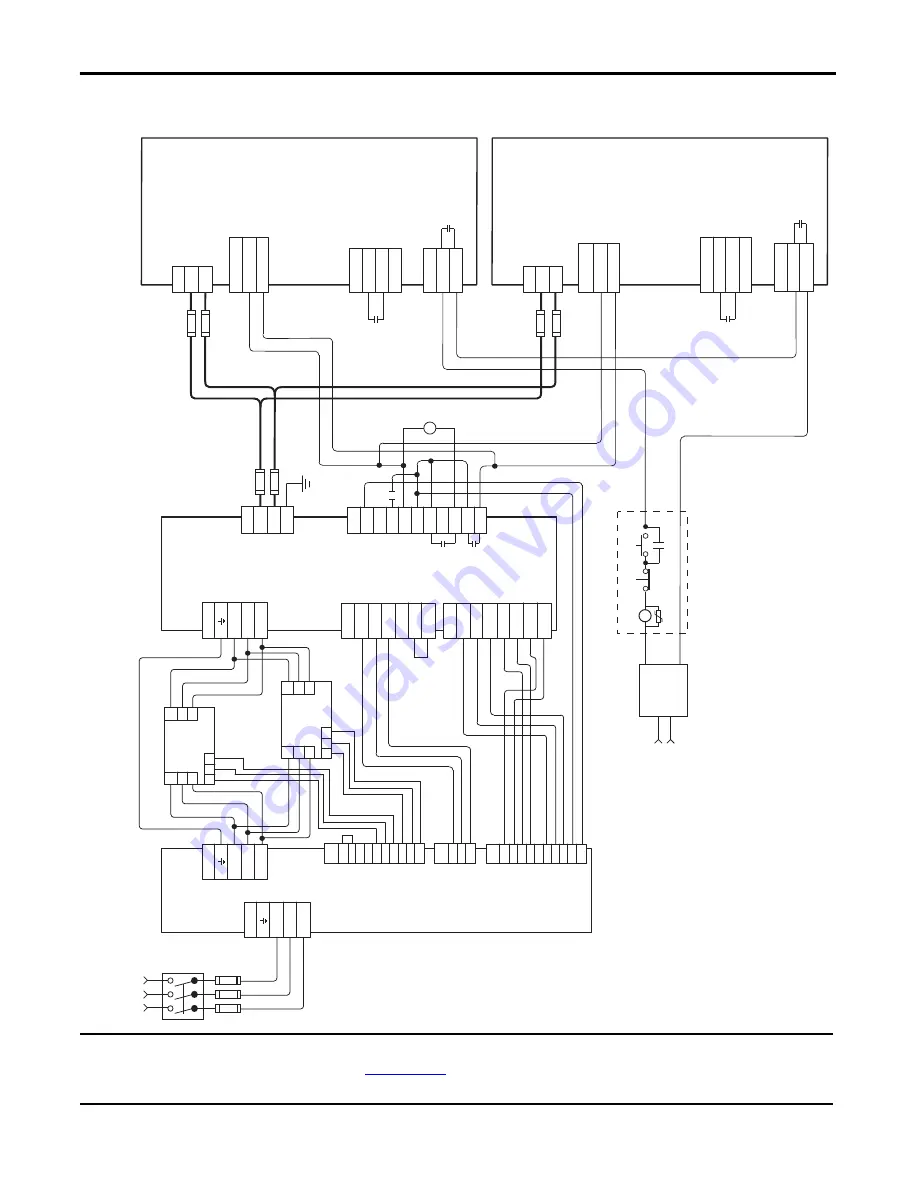
Figure 79 - 8720MC-RPS190BM Regenerative Power Supply to Multiple Kinetix 7000 Drives 

IMPORTANT

This configuration requires the power regenerative mode settings as described in the 8720MC Regenerative Power Supply 
Installation Manual, publication 

8720MC-RM001

, and setting of the power tab in RSLogix 5000 software is set to the 

appropriate bus regulator catalog number. Common mode capacitors should be disconnected on DC common bus drives.

L1

L2

L3

TB1

TB1

DC+

DC-

L1

L2

L3

TB1

L4

L5

L6

TB1

L1 AUX

L2 AUX

L3 AUX

PR1

PR2

PR3

TB2

MC

RST

PWR

0V

24V

COM

IP

RDY

FR

FR

TB3

Fault Relay Contact

L1

L2

L3

L4

L5

L6

RED

BLK

YLW

Fan 2

CN1

A1 A2 A3 A4 A5 B1 B2 B3 B4 B5

CN2

A1 A2 A3 A4 A5 B1 B2 B3 B4 B5

CN4

1 2 3

+24V3

0V3

SENS

+24V2

0V2

MC1

TB4

MC2

R1 S1 T1

MC1 MC2

+24V2

0V2 NC

+24V3

0V3

SENS-out

+24V

MC

RED

WHT

BLU

RED

BLK

YLW

GND

*Circuit Breaker See N\ote 2

*Inp

ut

Fusing See Note 2

Regenerative Power Supply

8720MC-RPS190BM

DC Bus

Connections

120V/240V AC

or

24V DC

Line Reactor

872

0MC

-LR1

0-1

00B

EMC Line F

ilter

87

20

MC-

EF1

90-

VB

* Ind

icates U

ser Su

ppl

ied

 Com

pon

en

t

*S

ingl

e-pha

se 

AC Line Filter

*T

hr

ee

-p

ha

se

 In

put

(+10/-15%) 380V AC RMS, 50 Hz or 460V AC RMS, 60 Hz See Note 1

L1

L2

L3

L4

L5

L6

Fan 3

Line Reactor

872

0MC

-LR1

0-1

00B

*DC Line Fuses

2

8

7

2

8

7

DC+

DC-

TB

24V DC

ENABLE

24V COM

IOD - Axis 1

GPR2+

GPR2-

GPR - Axis 1

REGEN COM 

REGEN OK

GPIO - Axis 1

DC+

DC-

TB

GPR2+

GPR2-

GPR - Axis 

n

REGEN COM 

REGEN OK

GPIO - Axis 

n

24V DC

ENABLE

24V COM

IOD - Axis  

n

1

1

CR2* See

Note 11

CR2* See

Note 11

Con

trol

Stop String See Notes 6 and 8

DC Bus Connections 

Power Co

nn

ections

DC Bus Connections 

Power Co

nn

ections

Kinet

ix 7000

 Drive

2099

-BM

xx

-S

* DC Line

 Fuses

(see table in Appendix A)

* DC Line

 Fuses

(see table in Appendix A)

Ad

ditional connecti

ons required, 

but 

not

shown in this diagram: 1. +24V DC Control Power 2. Motor Feedback, Brake (if used),  and Power 3. Drive I/O and Communications

Con

trol

Stop String See Notes 6 and 8

Kinet

ix 7000

 Drive

2099

-BM

xx

-S

5

6

5

6

STOP*

START (RPS On)*

CR1*

CR1*

RPS S

top

-Sta

rt St

ring

CR1*

CR2*

Summary of Contents for 2099-BM06-S

Page 1: ...Kinetix 7000 High Power Servo Drive Catalog Numbers 2099 BM06 S 2099 BM07 S 2099 BM08 S 2099 BM09 S 2099 BM10 S 2099 BM11 S 2099 BM12 S User Manual...

Page 2: ...on Inc with respect to use of information circuits equipment or software described in this manual Reproduction of the contents of this manual in whole or in part without written permission of Rockwell...

Page 3: ...oltage Values 61 Updated information on configuring the General Purpose I O regenerative power supply OK signal 64 Added Figure 41 Safe Off Motion allowed Jumper 65 Updated the information in the Sett...

Page 4: ...4 Rockwell Automation Publication 2099 UM001D EN P December 2012 Summary of Changes Notes...

Page 5: ...22 Circuit Breaker Fuse Selection 23 Enclosure Selection 24 Minimum Clearance Requirements 27 Minimizing Electrical Noise 28 Bonding Modules 28 Bonding Multiple Subpanels 30 Establish Noise Zones 30 C...

Page 6: ...it 73 General Wire Guidelines 74 Routing the Power and Signal Cables 74 Determine the Input Power Configuration 75 Grounded Power Configurations 75 Power Distribution Systems Without a Ground Referenc...

Page 7: ...onnectors 98 External Shunt Module Connections 101 SERCOS Fiber optic Cable Connections 101 Chapter5 ConfigureandStartuptheKinetix 7000DriveSystem Configure the Drive Modules 106 Node Addressing Examp...

Page 8: ...153 Weight Specifications 153 Certifications 154 Environmental Specifications 154 AC Line Filter Specifications 155 AC Line Reactors 155 External Shunt Modules 156 Precharge Capacities of the Regener...

Page 9: ...structions publication 2090 IN010 Providesinformationonproperhandling installing testing andtroubleshooting fiber optic cables ControlLogix SERCOS interface Module Installation Instructions publicatio...

Page 10: ...oC currently available from Rockwell Automation Kinetix Accelerator Toolkit Quick Start publication IASIMP QS002 Provides examples of using a Logix controller to connect to multiple devices servo driv...

Page 11: ...2012 11 Chapter 1 Start Use this chapter to become familiar with the design and installation requirements for Kinetix 7000 drive systems Topic Page About the Drive System 12 Typical Drive System Diagr...

Page 12: ...ies Compatible rotary servo motors include MP Series Bulletin MPL and MPM 400V class motors HPK Series motors and RDD Series direct drive motors Cables Motor Power Feedback and Brake cables Bulletin 2...

Page 13: ...56 for more information 2090 XXLF TCxxxx AC Line Filter 2094 BL75S Line Interface Module optional component 460V AC Three Phase Input Power RSLogix 5000 Software Input Logix 5000 Controller Output 175...

Page 14: ...ERCOS Fiber Optic Ring Commissioning 2099 BMxx S Kinetix 7000 Drive ControlLogix Chassis Motor Power Cable Encoder Feedback Cable 2090 K6CK Dxxx Low Profile Connector Kits for I O Motor Feedback and A...

Page 15: ...SERCOS Fiber optic Ring DC Bus 8720MC RPS065BM HV2 Regenerative Power Supply 8720MC LRxx Line Reactor Three phase Input Power 8720MC VA B Varistor Included with 8720MC RPS065BM HV2 8720MC HF B2 Harmon...

Page 16: ...tor Kits for I O Motor and Auxiliary Feedback 8720MC RPS190BM Regenerative Power Supply Three phase Input Power 8720MC EF190 VB EMC Line Filter This unit includes an AC line filter required for CE mag...

Page 17: ...DC Control Power 8720MC RF180 AC Line Filter Input Fusing Three Phase Input Power RSLogix 5000 Software Input Logix 5000 Controller Output 1756 MxxSE SERCOS Interface Module 2090 SCxxx x SERCOS Fiber...

Page 18: ...Cat No Kinetix 7000 460V 22 kW 40 A continuous output 2099 BM06 S Kinetix 7000 460V 30 kW 52 A continuous output 2099 BM07 S Kinetix 7000 460V 37 kW 65 A continuous output 2099 BM08 S Kinetix 7000 46...

Page 19: ...ssis and the motor with a 360 connection Combined motor power feedback cables must not exceed 90 m 295 3 ft Use 2090 series motor feedback cables or connector kits and terminate the feedback shield as...

Page 20: ...out LIM on page 19 the recommended installation and wiring in the 8720MC Regenerative Power Supply Reference Manual publication 8720MC RM001 and these additional requirements Install a three phase lin...

Page 21: ...Guidelines 22 Minimizing Electrical Noise 28 Mount the Kinetix 7000 Drive 39 ATTENTION Plan the installation of your system so that you can perform all cutting drilling tapping and welding with the s...

Page 22: ...side the enclosure for mounting your system components must be on a flat rigid vertical surface that won t be subjected to shock vibration moisture oil mist dust or corrosive vapors as specified in En...

Page 23: ...make sure that the selected components are properly coordinated and meet applicable codes including any requirements for branch circuit protection When applying the 140M product evaluation of the shor...

Page 24: ...trolLogix Once the total amount of heat dissipation in watts is known the minimum enclosure size can be calculated It is recommended that you also contact the enclosure manufacturer for the best enclo...

Page 25: ...52 2099 BM11 S Kinetix 7000 Servo Drive 50 1275 Total Wattage of Kinetix 7000 system 1727 Enclosure Component Description Backplane Power Load 1 Watts 1 For ControlLogix module specifications see the...

Page 26: ...minimum enclosure size must take into account the physical size and minimum clearance requirements of the two Kinetix 7000 drives and the additional ControlLogix and other devices required to meet th...

Page 27: ...Requirements See page 152 for power dissipation specifications IMPORTANT Mount the module in an upright position as shown Do not mount the module on its side 50 8mm 2 0in clearanceright of module is...

Page 28: ...rames shields and enclosures to reduce the effects of electromagnetic interference EMI Unless specified most paints are not conductive and act as insulators To achieve a good bond between the drive an...

Page 29: ...e mounting hole Star Washer Nut Nut Flat Washer Mounting Bracket or Ground Bus Use a wire brush to remove paint from threads to maximize ground connection Back Wall of Enclosure Welded Stud Subpanel S...

Page 30: ...ow impedance path This difference in impedance may affect networks and other devices that span multiple panels Figure 9 Multiple Subpanels and Cabinet Recommendations Establish Noise Zones When design...

Page 31: ...drive and the fuses contactors circuit breakers and AC line input to the EMC line filter to the right of the 8720MC RPS Shielded cable is required only if the very dirty cables enter a wireway The SE...

Page 32: ...M PROGRAM kW kW V A VD VD Route Encoder Analog Registration Shielded Cable Shielded Cable or Conduit Clean Wireway Cx No sensitive equipment within 150 mm 6 0 in Dirty Wireway Dx Shield Clamps beneath...

Page 33: ...he AC line output exits from the EMC line filter and connects to the Kinetix 7000 drive Shielded cable is required only if the very dirty cables enter a wireway The SERCOS fiber optic cables are immun...

Page 34: ...encoder registration grey wireway The dirty zone D is above and below the power supply and noisy modules black wireway The SERCOS fiber optic cables are immune to electrical noise Figure 13 Establish...

Page 35: ...Kinetix 7000 System Wire Cable Connector Zone Method Very Dirty Dirty Clean Ferrite Sleeve Shielded Cable Control Power CP X DC DC PTB X L1 L2 L3 shielded cable X X L1 L2 L3 unshielded cable X DPI DPI...

Page 36: ...ose to the power input as possible Good HF bonding to the panel is critical For painted panels refer to the examples on page 29 Segregate input and output wiring as far as possible Wire Cable Connecto...

Page 37: ...p shunt wiring as flat to the cabinet as possible Route thermal switch and fan wires separate from shunt power Figure 14 External Shunt Resistor Outside the Enclosure C1 C1 VD D3 D2 D1 VD VD D1 D2 Kin...

Page 38: ...Inside the Enclosure MotorBrakeandThermalSwitch The thermal switch and brake are mounted inside the motor but how you connect to the axis module depends on the motor series See Wire Motor Output Powe...

Page 39: ...ing Modules beginning on page 28 Follow the lifting instructions found in the Kinetix 7000 High Power Servo Drive Installation Instructions publication 2099 IN003 3 Tighten all mounting fasteners SHOC...

Page 40: ...C M1 M2 M3 2099 BM06 S 2099 BM07 S 2099 BM08 S 517 5 20 37 254 12 10 0 224 3 8 83 495 0 19 49 192 0 7 56 15 3 0 60 M6 0 25 2099 BM09 S 644 5 25 37 331 9 13 07 286 7 11 29 625 0 24 61 225 0 8 86 37 5...

Page 41: ...or Data This chapter provides power feedback and I O connector locations and signal descriptions for a Kinetix 7000 drive Topic Page Locate and Identify Connectors and Indicators 42 Control Signal Spe...

Page 42: ...iary Feedback Motor Feedback I O Power terminal block located behind protective cover 2099 BM08 S shown 1 2 3 6 7 8 9 4 5 10 Item Designator Label Description Connector See Page 1 Node Address SERCOS...

Page 43: ...GPR1 GPR1 24VDC GPR FDBK2 FDBK2 FDBK1 FDBK1 ENABLE2 ENABLE ENABLE1 SO_24VDC SO_COM SO 2099 BM08 S shown 1 Top View 2 3 4 5 6 7 Item Designator Label Description Connector See Page 1 SO Safe off Termin...

Page 44: ...ix 7000 Connector Data Figure 19 Kinetix 7000 Bottom Panel Connectors 2099 BM06 S and 2099 BM07 S shown 1 Bottom View 2 Item Designator Label Description Connector See Page 1 CP Control Power Terminal...

Page 45: ...tput Power Reg_2_Pwr 4 Drive supplied 24V DC Home_Switch_Pwr 17 Registration 2 Input Reg_2_In 5 Home Switch Input Home_Switch_In 18 Registration 2 Common Reg_2_Com 6 Home Common Home_Switch_Com 19 Dif...

Page 46: ...inal Block Terminal Description Signal Name 1 Digital Output 1 Digital_Out_1 2 24V DC for digital output 1 customer supplied DO_24VDC_1 3 24V DC for digital output 2 customer supplied DO_24VDC_2 4 Dig...

Page 47: ...losed 1 TS 4 Cosine differential input COS 12 Reserved 5 Hiperface data channel DATA 13 Reserved 6 Common ECOM 14 Encoder power 5V EPWR_5V 2 7 Encoder power 9V EPWR_9V 2 15 Reserved 8 Reserved 1 Not a...

Page 48: ...r Heidenhain EnDat IMPORTANT Only 2099 BMxx S drives with firmware revision 1 104 or higher support the use of 2090 K7CK KENDAT feedback modules Pin Description Signal Pin Description Signal 1 Sine di...

Page 49: ...differential input SIN 10 Hiperface data channel DATA 3 Cosine differential input COS 11 Reserved 4 Cosine differential input COS 12 Reserved 5 Hiperface data channel DATA 13 Reserved 6 Common ECOM 14...

Page 50: ...onitoring contact for safety relay 1 FDBK1 4 Return for safety relay 1 FDBK1 5 Coil of safety relay 2 ENABLE2 6 Common for safety relays 1 and 2 ENABLE 7 Coil of safety relay1 ENABLE1 8 24V DC 500 mA...

Page 51: ...ify the input power motor power DC bus ground and cooling fan input terminals The 2099 BM09 S or 2099 BM10 S drives frame 5 and the 2099 BM11 S or 2099 BM12 S drives frame 6 provide connections for yo...

Page 52: ...99 BM08 S Figure 28 2099 BM09 S Figure 29 2099 BM10 S DC DC U V W R L1 S L2 T L3 Cable clamps for Motor and AC inputs PS PS NC NC DC DC U V W PE PE R L1 S L2 T L3 PS PS Motor FAN AC Line Fan Terminals...

Page 53: ...PE Ground GND Motor Ground Motor Ground U T1 Motor Phase U Output U T1 V T2 Motor Phase V Output V T2 W T3 Motor Phase W Output W T3 R L1 Main 380 480V AC 10 Input Power Three phase to R S and T Inpu...

Page 54: ...Control of Electrical Noise Reference Manual publication GMC RM001 IOD Pin Signal Description Capture Time Edge Level Sensitive IOD 2 ENABLE Single opticallyisolated single endedactivehighsignal Curr...

Page 55: ...ble 19 Digital Input Descriptions and Table 20 Digital Input Specifications starting on page 54 for On Off signal voltages and current levels Kinetix 7000 drive Hardware Enable functions and faults ac...

Page 56: ...tions and Table 20 Digital Input Specifications starting on page 54 for On Off signal voltages and current levels The schematic below depicts the Home circuit It is provided as a reference only Figure...

Page 57: ...n page 54 for On Off signal voltages and current levels Kinetix 7000 drive Positive and Negative Overtravel functions and faults actions are programmed through RSLogix software Kinetix 7000 drive firm...

Page 58: ...ration_Position register in Logix software Figure 35 Logix Position Register Entry Power for the inputs is supplied by an internally supplied 24V DC supply See Table 19 Digital Input Descriptions and...

Page 59: ...tion Digital Input Circuit Diagram 1 24V DC source range 21 6V 26 4V supplied by the drive not to exceed 300 mA total Maximum current input 10 mA 3k 0 001 F 511 VCC INPUT IO_COM I O SUPPLY 1k 24V DC H...

Page 60: ...input is up to 4 kHz and input impedance is 12 k Analog inputs are available as a real time attribute and Get System Value GSV within RSLogix software The schematic below depicts the Analog Input circ...

Page 61: ...eters 691 AnaInput 1 Value and 692 AnaInput 2 Value In the example above analog input 1 displays 69 79 This value equals 100 of 10V DC Therefore the actual value of analog input 1 is 6 98V DC When vie...

Page 62: ...A Analog output functions are programmed in RSLogix software using a message instruction The default pin assignments and the default gain values for the velocity torque and following error parameters...

Page 63: ...t_2 Zero_Speed is the motor at 0 rpm velocity In_Position can be set to the commanded position by the Position Lock Tolerance set in Axis Properties Limits Default parameter selections can also be set...

Page 64: ...OK Diagram General Purpose Relay GPR Connector Two general purpose relay connections are accessed through the GPR connector GPR1 is a normally open dry relay contact supporting 2 A at 30V DC 10 with...

Page 65: ...tion see the Kinetix Safe off Feature Safety Reference Manual publication GMC RM002 Figure 41 Safe Off Motion allowed Jumper Control Power Specifications The following table provides specifications fo...

Page 66: ...es per rotation interpolated to over 2 million counts in the drive For example the MPL B980D SJ72AA has this feedback type M type multi turn 1024 cycles per rotation interpolated to over 2 million cou...

Page 67: ...Maximum Input Frequency 5 0 MHz TTL input per channel 250 kHz Sine Cosine input Commutation Feedback Hall sensor Parameter Description Minimum Maximum AM BM and IM ON state Input Voltage Inputvoltage...

Page 68: ...hannel is included MPx B and HPK B and E motors all use 9V power sources from the MF connector Compatible Auxiliary Feedback devices include Stegmann Hiperface Sine Cosine and 5V TTL encoder types Not...

Page 69: ...ails power supply specifications for the motor and auxiliary feedback connectors Table 29 Motor and Auxiliary Feedback Power Supply Specifications Power Supply Signal Name Voltage V DC Current mA Min...

Page 70: ...70 Rockwell Automation Publication 2099 UM001D EN P December 2012 Chapter 3 Kinetix 7000 Connector Data Notes...

Page 71: ...onnections 101 SERCOS Fiber optic Cable Connections 101 ATTENTION Plan the installation of your system so that you can perform all cutting drilling tapping and welding with the system removed from the...

Page 72: ...nector kit catalog numbers Shielded Motor Cable The use of a four wire type Variable Frequency Drive VFD 600 volt UL listed cable is strongly recommended for all motor currents at or below 130 Amperes...

Page 73: ...ives are normally mounted in cabinets and ground connections are made at a common ground point in the cabinet If the conduit is connected to the motor junction box and the drive end is connected to th...

Page 74: ...erence use shielded wire in motor and control circuits A shielded cable is required for all feedback signal wires Routing the Power and Signal Cables Be aware that when you route power and signal wiri...

Page 75: ...a neutral point Figure 44 Grounded Three phase Power Wiring WYE Secondary Recommended ATTENTION When using a LIM with your Kinetix 7000 drive the AC line input power must come from a grounded configu...

Page 76: ...System This is an example of a grounded B phase delta secondary Figure 45 Grounded B phase Power Wiring Delta Secondary L1 L3 L2 2099 BM08 S Shown with Lower Front Panel Removed Transformer Delta Seco...

Page 77: ...bution system Figure 46 Ungrounded Power Wiring ATTENTION Disconnect the protective MOVs and capacitors if the drive is installedona highresistive grounded orungrounded system where the line to ground...

Page 78: ...the power terminals The voltage must be zero Drive Jumper Wire ID No Component Location 2099 BM06 S 2099 BM07 S and 2099 BM08 S PEA Common mode capacitor Remove the two jumpers located above the powe...

Page 79: ...pacitor jumper is indicated by callout 1 PEA and the MOV jumper is indicated by callout 2 PEB Remove each jumper by carefully pulling it straight out Figure 47 Ground Jumper Location on 2099 BM06 S 20...

Page 80: ...cated by callout 5 and the MOV ground wire is indicated by callout 6 Figure 49 Ground Wire Location on Power Terminal Block of 2099 BM11 S and 2099 BM12 S WIRE RANGE 14 1 0 AWG 2 5 35 MM2 TORQUE 32 IN...

Page 81: ...ment chassis See Agency Compliance on page 18 for CE grounding requirements Grounding Your System to the Subpanel In Figure 50 the drive is shown properly grounded to the bonded cabinet ground on the...

Page 82: ...BM08 S drives to the drive to provide a 360 termination Factory supplied power cables must also be terminated in the motor power MP connector plug Customer supplied power cables must be shielded and...

Page 83: ...r eliminating the brake connector Figure 53 Bayonet and Circular DIN Motor Connectors Drive Conduit or Cable Braid Clamped at Drive Frame Provides 360 Shield Termination Clamp Also Connects to the Nea...

Page 84: ...090 CPWM7DF xxAAxx standard non flex 2090 CPWM7DF xxAFxx 1 continuous flex Bayonet MPL A B5xxx MPL B6xxx and MPL B8xxx MPL B960B MPL B960C MPL B980B and MPL B980C N A 2090 XXxPMP xxSxx 2 MPL B960D and...

Page 85: ...ations with large numbers of drives in a similar location imposed EMC regulations or a high degree of communications and networking are also good candidates for shielded cable Shielded cable may also...

Page 86: ...the motor If an input device is used operation must not exceed four cycles per minute maximum or damage will occur to the drive precharge circuit The start stop enable control circuitry for the drive...

Page 87: ...o not follow ESD control procedures components can be damaged If you are not familiar with static control procedures See publication 8000 4 5 2 Guarding Against Electrostatic Damage or any other appli...

Page 88: ...recommended torque for the specific terminal 5 Pull on each wire to make sure it does not come out of its terminal If any wires are loose reinsert connect and tighten the wire to the recommended torq...

Page 89: ...nal Block PTB Connections on page 51 for more information Kinetix 7000 Drive Cat No Signal Terminal Recommended Wire Size mm2 AWG Torque N m lb in 2099 BM06 S 2099 BM07 S 2099 BM08 S L1 L2 L3 Ground R...

Page 90: ...m2 AWG Torque N m lb in 2099 BM06 S 2099 BM07 S 2099 BM08 S DC DC DC DC 25 2 5 3 14 1 8 16 2099 BM09 S DC DC DC DC 50 4 1 0 12 3 6 32 2099 BM10 S DC DC DC DC 70 10 2 0 8 15 133 2099 BM11 S 2099 BM12 S...

Page 91: ...to the drive wire the DRIVE OK relay into your safety control string In common bus configurations a REGEN connection on the General Purpose Input Output connector is also required for the drives This...

Page 92: ...a motor brake Kinetix 7000 Drive Cat No Signal Terminal Recommended Wire Size mm2 AWG Torque N m lb in 2099 BM06 S 2099 BM07 S 2099 BM08 S U Brown V Black w Blue Green Yellow U V W 25 2 5 3 14 1 8 16...

Page 93: ...be ordered with the brake option 2090 CPBM7DF xxAAxx 1 2090 XXNPMF xxSxx standard non flex 2090 CPBMxDF xxAFxx 1 continuous flex HPK Series N A The motor has a separate brake wiring connection Custome...

Page 94: ...High Resolution Feedback MPL B5xxxx M Sx2xAA MPL B6xxxx M Sx2xAA MPL B8xxxx M Sx2xAA and MPL B9xxxx M Sx2xAA Drive MF Connector Pin Signal A Sine 1 B Sine 2 C Cos 3 D Cos 4 E Data 5 F Data 10 K Reser...

Page 95: ...ry Motor Circular DIN Connector Pin RDB Bxxxxx 3 7 Motors 2090 K7CK KENDAT Pin Signal 1 Sine 1 2 Sine 2 3 Cos 3 4 Cos 4 5 Data 9 6 Data 10 7 CLK 7 8 CLK 8 9 EPWR_5V 5 10 ECOM 6 11 Reserved 12 Reserved...

Page 96: ...s The panel mounted breakout board kit catalog number 2090 UXBK D15xx includes a DIN rail terminal block and cable The cable connects between the terminal block and the motor feedback MF connector Wir...

Page 97: ...Chapter 4 Figure 55 Panel mounted Breakout Board Connection Example 2090 UXBC D15xx Breakout Cable See the Motor Feedback Breakout Board Installation Instructions publication 2090 IN006 for Connector...

Page 98: ...or higher support the use of this feedback module 2090 XXxFMP Sxx 2090 XXNFMF Sxx 2090 CFBMxDF CxAxxx 2090 K6CK D15M Low profile connector kit for motor feedback 15 pin male D sub Use with any Kineti...

Page 99: ...ecure Mounting Screws See the Low Profile Connector Kit Installation Instructions Publication 2094 IN007 for Connector Kit Specifications 2090 K6CK D15x Low profile Connector Kit Pin 1 Pin 10 Pin 5 Pi...

Page 100: ...nector Discrete I O Wire Tie Wrap Slot Three Conductor I O Cable s Turn Clamp Over to Hold Small Wires Secure Mounting Screws See the Low Profile Connector Kit Installation Instructions Publication 20...

Page 101: ...re assumes you have your Logix SERCOS interface module PCI card and Kinetix 7000 drive mounted and are ready to connect the fiber optic cables The SERCOS fiber optic ring is connected using the SERCOS...

Page 102: ...S Receive Connector Rx front SERCOS Transmit Connector Tx rear Front View Bottom View SoftLogix Platform 1756 PM16SE SERCOS interface PCI Card as viewed from the back of your personal computer SERCOS...

Page 103: ...can also mount the two Logix SERCOS modules in two separate chassis or you can mount them in the same chassis SERCOS interface TM Tx rear Rx front OK CP Kinetix 6000 System 1756 MxxSE SERCOS interface...

Page 104: ...ections ControlLogix CompactLogix IMPORTANT To avoid signal loss do not use bulkhead adapters to connect glass cables Usebulkheadadaptersformakingplastic to plasticcableconnectionsonly SERCOS interfac...

Page 105: ...you begin make sure you know the characteristics of the following system components Logix processor Logix module s including the SERCOS module Kinetix 7000 drive s and accessories Servo motor s actuat...

Page 106: ...sets the least significant digit LSD Refer to the table and figure below for switch operation Table 48 Node Addressing Switch Settings Figure 63 N ode Addressing Switch Settings 3 Cycle control power...

Page 107: ...000 drive For This Optical Power Level Set Switch 1 Low OFF High ON IMPORTANT All drives on the SERCOS ring must have the same baud rateand power setting 1 2 3 1 2 3 DIP Switches Set for 4 Mbps Applic...

Page 108: ...OS interface TM Tx rear Rx front OK CP SERCOS interface TM Tx rear Rx front OK CP 03 Drive axis 3 Node Address 02 Drive axis 2 Node Address 01 Drive axis 1 Base Node Address SERCOS Fiber optic Rings 1...

Page 109: ...t used The Kinetix 7000 2 axis drive system contains two drives The base node address of the system must be set for an address of 9 SERCOS interface TM Tx rear Rx front OK CP 08 Not Used AM rightmost...

Page 110: ...igure the Logix controller 1 Apply power to your Logix chassis containing the SERCOS interface module and open your RSLogix 5000 software 2 From the File menu choose New The New Controller dialog box...

Page 111: ...Controller Properties dialog box opens 6 Click the Date Time tab 7 Check Enable Time Synchronization This assigns the controller as the Grandmaster clock The motion modules set their clocks to the mo...

Page 112: ...roller Organizer and choose New Module The Select Module dialog box opens 2 Expand the Motion category and select 1756 MxxSE 1756 L60M03SE 1768 M04SE or 1784 PM16SE as appropriate for your actual hard...

Page 113: ...ng table 9 Verify that the Transmit Power setting high matches the Optical Power DIP switch 1 as set on the drive 10 Enter the Transition to Phase setting The Transition to Phase default setting is 4...

Page 114: ...ow these steps to configure the motion group 1 Right click Motion Groups in the Controller Organizer and choose New Motion Group The New Tag dialog opens 2 Type the new motion group Name 3 Click OK Th...

Page 115: ...ssigned to the Kinetix 7000 axis in the Configure the Kinetix 7000 Drive Modules section 5 Right click the Motion group name created and select New Axis 6 Select an Axis_Servo_Drive SERCOS controlled...

Page 116: ...older The Motion Planner coarse update period must be set according to the application needs Guidelines for the coarse update period for the processor used and the number of servo drive axes created i...

Page 117: ...w Module The Select Module dialog box opens 2 Expand the Drives category and select your drive as appropriate for your actual hardware configuration 3 Click OK The New Module dialog box opens 4 Config...

Page 118: ...Check Open Module Properties 5 Click OK 6 Select the Associated Axes tab 7 Assign Axis_1 to Node 1 in the Associated Axis folder This assigns Axis 1 in the motion group to the Kinetix 7000 drive at no...

Page 119: ...ary system To simplify the setup a linear system is utilized The calculate tool on the Drive Motor tab will be used to set the drive resolution and conversion constant If a rotary system is used the D...

Page 120: ...lculate to configure the drive resolution and conversion constant The position unwind is also calculated if rotary load is used 20 In this example a linear load is used and a 25 4 mm 1 in movement on...

Page 121: ...ication 2099 UM001D EN P December 2012 121 Configure and Startup the Kinetix 7000 Drive System Chapter 5 The Drive Motor tab and Conversion tabs should look similar to these examples or reflect your a...

Page 122: ...brake delay times refer to refer to the Kinetix Motion Control Selection Guide publication GMC SG001 26 Configure the delay times a Type the Brake Engage Delay Time b Type the Brake Release Delay Tim...

Page 123: ...an axis is associated to the auxiliary axis node set the Axis Configuration on the General tab of the Axis Properties dialog box to Feedback Only 30 Select the Units tab and configure the same as in...

Page 124: ...otary as in step 19 22 of this procedure 34 Click the Aux Feedback tab 35 From the Feedback Type pull down menu choose the feedback type appropriate for your auxiliary feedback motor 36 Click Apply 37...

Page 125: ...ion you must download your program to the Logix processor If your drive requires Then choose No bus regulator configuration none External Shunt configuration 1336 MOD KB005 KB010 or KB050 1336 WB009 W...

Page 126: ...er 2 Verify the status of the drive logic power status indicator SHOCK HAZARD To avoid hazard of electrical shock complete all mounting andwiringpriortoapplyingpower Oncepowerisapplied connectortermin...

Page 127: ...Enable Input signal IOD pin 2 is off 3 Go to mainstep 4 Kinetix 7000 Drive Status Indicator Status Do This Actively cycling phase 0 The drive is looking for a closed SERCOS ring Wait for phase 1 or ta...

Page 128: ...enabled when status should be disabled 1 Verify Hardware Enable Input IOD 2 is open 2 Verify MSO instruction is not commanded in RSLogix5000 software 3 Return to Apply Power to the Drive on page 126...

Page 129: ...g your axes with ControlLogix CompactLogix or SoftLogix SERCOS modules refer to Additional Resources on page 9 Test the Axes Follow these steps to test the axes 1 Verify the load was removed from each...

Page 130: ...us changes from Executing to Command Complete 7 Click OK The Online Command Apply Test dialog opens Feedback and Command Feedback tests only When the test completes the Command Status changes from Exe...

Page 131: ...Hardware Enable Input signal IOD 2 3 Go to Tune the Axes on page 131 Your test failed this dialog box opens 1 Click OK 2 Verify the Bus Status LED turned solid green during the test 3 Verify that the...

Page 132: ...ur application 6 Apply Hardware Enable Input signal IOD 2 for the axis you are tuning 7 Click Start Tuning to auto tune your axis The Online Command Tune Servo dialog box opens When the test completes...

Page 133: ...12 Determine if your test completed successfully 13 Repeat Test and Tune the Axes for each axis If Then Your test completes successfully this dialog box opens 1 Click OK 2 Removethe Hardware Enable In...

Page 134: ...he example dialog box below In this example the I O Interface group folder is open and the Analog Outputs file is selected in the tree view pane on the left The parameters and corresponding elements a...

Page 135: ...wn arrows and to arrive at selections Refer to the instructions that came with your HIM module for more information Follow these steps to monitor or change parameters with the HIM module 1 Select para...

Page 136: ...136 Rockwell Automation Publication 2099 UM001D EN P December 2012 Chapter 5 Configure and Startup the Kinetix 7000 Drive System Notes...

Page 137: ...roduct manuals listed in the Additional Resources section on page 9 for troubleshooting information on other products ATTENTION Capacitors on the DC bus may retain hazardous voltages after input power...

Page 138: ...ndicator Error Codes Error Code Fault Message RSLogix Anomaly or Symptom Potential Cause Possible Resolution No ErrorCode Displayed Power PWR indicator not ON No AC power or auxiliary logic power Veri...

Page 139: ...e phase power present the DC bus voltage is below precharge limits Bus voltage for 460V system is below 275V DC Verify voltage level of the incoming AC power Verify integrity and consistency of AC pow...

Page 140: ...uce duty cycle ON OFF of commanded motion Increase time permitted for motion Use larger Kinetix 7000 drive and motor Check tuning E30 MotFeedbackFault Communication was not established with an intelli...

Page 141: ...y that each SERCOS drive is assigned a unique node address E54 DriveHardFault Excessive Current Feedback Offset Defective current feedback sensing If error persists return the drive to Rockwell Automa...

Page 142: ...the controller Change the command profile to reduce speed or increase time The airflowaccess to the Kinetix 7000 driveis limited or blocked Check airflow and remove any fan blockage E76 DriveHardFault...

Page 143: ...ing Steady Green Communication ready No faults or failures N A 1 Refer to Fiber optic Cable Installation and Handling Instructions publication 2090 IN010 for more information Bus Status LED Status Con...

Page 144: ...drive If low profile connector is used verify the connection for correct pinout pinched insulation and loose wires Verify motor feedback cable for continuity and shorts Replace the motor Displaying a...

Page 145: ...but the load machine does not Check and correct the mechanics Primary operation mode is set incorrectly Check and properly set the limit Velocity or current limits are set incorrectly Check and proper...

Page 146: ...n Motor locks into position runs without control or with reduced torque Motor power phases U and V U and W or V and W reversed Check and correct motor power wiring Sine Cosine or Rotor leads are rever...

Page 147: ...point is dictated by the lesser of the user velocity limits or the motor rated base speed DISABLE DRIVE No PositionErrorFault Follow Error E19 Axis position error limit has been exceeded This fault c...

Page 148: ...mory Init E71 RAM or flash memory validation failure SHUTDOWN No DriveOvertempFault Drive Overtemp E72 Invertertemperaturelimitexceeded FirmwareI2 tprotectiondoesnotgenerateafault rather it dynamicall...

Page 149: ...pecifications and mounting dimensions for your Kinetix 7000 system components Topic Page Power Specifications 150 Power Dissipation Specifications 152 General Specifications 153 AC Line Filter Specifi...

Page 150: ...duration 68 0 A 51 0 A 80 0 A 60 0 A 104 A 78 0A 154 A 115 A 163 A 138 A 312 A 234 A 372 A 273 A Peak output current 0 pk 3 s duration 60 s duration 96 0 A 72 0 A 113 A 84 8 A 147 A 110 A 217 7 A 162...

Page 151: ...pecifications Table 59 Ferraz Shawmut Fuse Recommendations IMPORTANT LIM modules catalog numbers 2094 BLxxS and 2094 XL75S Cx provide branchcircuitprotectiontotheKinetix7000drive FollowallapplicableNE...

Page 152: ...8 S 69 7 FWJ 125A 125 4800 35000 10000 A 2099 BM09 S 105 FWJ 175A 175 7500 65000 12000 A 2099 BM10 S 137 FWJ 200A 200 11700 80000 13000 A 2099 BM11 S 204 FWJ 500A 500 39500 329000 21000 A 2099 BM12 S...

Page 153: ...ables assume the use of recommended 2090 series cables Table 61 Cable Lengths for Compatible Rotary Motors Weight Specifications Motor Cat No AbsoluteHigh resolution 5V Encoder m ft AbsoluteHigh resol...

Page 154: ...ctronic safety related systems EN ISO 13849 1 2008 Safety of machinery Safety related parts of control systems Part 1 General principles for design C Tick Radiocommunications Act 1992 Radiocommunicati...

Page 155: ...BM10 S 2090 XXLF TC3150 2099 BM11 S 2090 XXLF TC3200 2099 BM12 S 2090 XXLF TC3250 8720MC RPS Cat No AC Line Filter Manufacturer and Cat No 8720MC RPS065BM HV2 Schaffner FN3100 80 35 Soshin Electric H...

Page 156: ...upply Cat No 1 1 Regenerative Power Supply RPS selection is for a single motor drive combination When combining multiple drives on the same RPS module the selectionwill change 8720MC Line Reactor Cat...

Page 157: ...HV2and8720MC RPS190 youmayhaveupto twoslave units with a master unit Multiply these values by the numberofslaveunits 2 Use this case only when the bus capacitance exceeds the internal precharge rating...

Page 158: ...28 8 0 0 31 7 0 0 28 X2 66 0 2 60 97 0 3 82 137 2 5 40 187 0 7 36 31 9 1 26 151 1 5 95 165 1 6 50 160 1 6 30 165 9 6 53 37 3 1 47 X2 22 4 0 88 28 7 1 13 66 0 2 60 130 0 5 19 186 0 7 32 31 9 1 26 28 7...

Page 159: ...5 1 48 6 5 0 26 2X 12 0 0 47 644 5 25 37 7 0 0 28 625 0 24 61 690 3 27 18 2099 BM10 34 9 1 37 2X 60 4 2 38 159 5 6 28 31 9 1 26 85 1 3 35 65 0 2 56 2X 130 5 12 170 6 69 24 5 0 96 2X 45 5 1 79 22 2 0 8...

Page 160: ...0 0 33 46 824 0 32 44 14 5 0 04 30 0 1 18 360 6 14 20 2X 8 5 0 33 2X 399 2 15 72 849 97 33 46 282 8 11 13 977 1 38 47 34 9 1 37 22 2 0 87 4X 62 7 2 47 2X 73 8 2 90 36 9 1 45 4X 148 4 5 84 31 69 1 25 4...

Page 161: ...76 Dual 8720MC RPS065Bx Regenerative Power Supplies to a Single Kinetix 7000 Drive 167 Figure 77 Kinetix 7000 Drive AC Powered with a 8720MC RPS190BM Regenerative Power Supply 168 Figure 78 8720MC RP...

Page 162: ...ower Configuration on page 75 for more information 6 7 Use of an external 24V DC control power supply is recommended for energizing the main control board This allows the SERCOS ring to remain active...

Page 163: ...ing of Power Wiring Required to Comply with EMC Requirements Bonded Cabinet Ground Bus Three Phase Motor Power Connections Indicates User Supplied Component Three phase AC Input and DC Bus Output Conn...

Page 164: ...240V AC or 24V DC Line Reactor 8720MC for RPS unit RPS Stop Start String Bonded Cabinet Ground Bus Indicates User Supplied Component Three phase Input 10 15 380V AC RMS 50 Hz or 460V AC RMS 6 Hz See...

Page 165: ...RST PWR 0V 24V COM IP RDY FR FR TB3 8 7 REGEN COM REGEN OK GPIO CR1 DC Bus Connections MC AUX 24V ENABLE ENABLE 24V COM IOD 1 2 Power Connections Fault Relay Contact GPR2 TB DC DC RPS Stop Start Stri...

Page 166: ...RPS On CR1 CR1 CR1 MC E N 1 1 CR2 See Note 11 CR2 See Note 11 RPS Stop Start String Regenerative Power Supply 8720MC RPS065BM 120V 240V AC or 24V DC Indicates User Supplied Component Three phase Conta...

Page 167: ...sed and Power 3 Drive I O and Communications CR1 GPR2 CR1 MC2 CB2 Bonded Cabinet Ground Bus Circuit Breaker CB2 Input Fusing See Note 2 Three phase Contactor MC2 Harmonic Filter Varistor Indicates Use...

Page 168: ...rive I O and Communications Power Connections Motion Control Stop Start String from PLC or other control string L1 L2 L3 TB1 TB1 DC DC CR1 L1 L2 L3 TB1 L4 L5 L6 TB1 L1 AUX L2 AUX L3 AUX PR1 PR2 PR3 TB...

Page 169: ...0V 24V COM IP RDY FR FR TB3 Fault Relay Contact L1 L2 L3 L4 L5 L6 RED BLK YLW Fan 2 CN1 A1 A2 A3 A4 A5 B1 B2 B3 B4 B5 CN2 A1 A2 A3 A4 A5 B1 B2 B3 B4 B5 CN4 1 2 3 24V3 0V3 SENS 24V2 0V2 MC1 TB4 MC2 R1...

Page 170: ...ee N ote 2 Input Fusing See Note 2 Regenerative Power Supply 8720MC RPS190BM DC Bus Connections 120V 240V AC or 24V DC Line Reactor 8720MC LR10 100B EMC Line Filter 8720MC EF190 VB Indicates User Supp...

Page 171: ...e Power Supply 8720MC RPS190BM DC Bus Connections Kinetix 7000 Drive 2099 BMxx S Axis n EMC Line Filter 8720MC EF190 VB Indicates User Supplied Component DC Bus Connections Three phase Input 10 15 380...

Page 172: ...onnector Motor Power MP Connector CableShield Clamp Cable shield clamp must be used to meet CE requirements No external connection to ground required 3 MPL Bxx 460V Servo Motors with High Resolution F...

Page 173: ...t it is recommended that a customer supplied external device such as an interposing relay be used between the drive and motor See Figure 82 below A customer supplied diode or metal oxide varistor MOV...

Page 174: ...ble shield clamp must be used to meet CE requirements No external connection to ground required MPL Bxx and MPM Bxx 460V Servo Motors with High Resolution Feedback Motor Feedback MF Connector 3 Motor...

Page 175: ...r Feedback Thermostat Motor Power Cable customer supplied 2090 XXNFMF Sxx or 2090 CFBM4DF CDAFxx Feedback Cable Cable Shield Clamp Spring set Brake Single phase Customer supplied Interface to 460V AC...

Page 176: ...tings Figure 85 Customer supplied HPK Series Motor Brake Wiring Example HPK SeriesMotorBlowerConnections The HPK series motor blower must be used to ensure proper motor performance The blower connecti...

Page 177: ...HT BROWN TS Motor Power MP Connector Cable Shield Clamp RDB BxxxxDirect Drive Servo Motors with High Resolution Feedback Motor Feedback MF Connector Three phase Motor Power Motor Feedback Thermistor 2...

Page 178: ...on allowed jumper installed In this configuration the safe off feature is disabled not used Figure 87 Kinetix Safe off Feature K1 K2 K1 A K2 A K2 C K1 C 24V M Safe Off Option 6 5 7 3 4 1 2 8 9 Wiring...

Page 179: ...c Page Before You Begin 179 Upgrade Firmware 180 Description Catalog Numbers Version RSLogix 5000 Software 9324 RLD300NE 15 0 or later RSLinx Software 0355 RSLETENE 2 50 00 or later ControlFlash Kit 1...

Page 180: ...Flash software or select ControlFlash from the Tools menu of RSLogix 5000 software The Welcome to ControlFlash dialog opens 3 Click Next The Catalog Number dialog opens IMPORTANT The seven segment LED...

Page 181: ...P December 2012 181 Upgrade Firmware Appendix C 4 Select the catalog number of the Kinetix 7000 2099 BMxx S drive to upgrade 5 Click Next 6 Select the SERCOS interface module and Kinetix 7000 drive to...

Page 182: ...mware 8 Select the firmware revision to use in this update Select the new firmware from the list or browse for it using the Current Folder option 9 Click Next 10 Confirm the catalog number and serial...

Page 183: ...Upgrade Firmware Appendix C 12 Click Yes to confirm updating of the target device 13 Click OK to acknowledge the Motion Stop notice A dialog will display the progress of the flash update While this d...

Page 184: ...r failure as described below 14 Click OK The ControlFlash software returns to the Welcome screen where you can flash another drive or select Cancel to exit the program Flashing If Succeeded 5 Update c...

Page 185: ...roduct Certification 10 changing parameters HIM 135 circuit breaker specifications Kinetix 7000 151 circuit breakers 126 sizing 23 configuring base node address 106 baud rate IAM 106 delay times 122 I...

Page 186: ...it breaker fuse 151 contactor ratings 152 enclosure sizing 152 environmental 154 maximum fdbk cable length 153 power dissipation 152 power section 150 weight 153 typical configuration DC common bus 16...

Page 187: ...tus indicator 127 shutdown 146 software RSLogix 5000 110 specifications feedback motor and auxiliary 66 power supply 68 I O digital inputs 54 Kinetix 7000 circuit breaker fuse 151 contactor ratings 15...

Page 188: ...mmon dc bus power 78 external shunt resistor 101 ground reference 77 grounding 81 I O connections 93 impedance grounded power system 78 input power determining type 75 without LIM 88 low profile conne...

Page 189: ......

Page 190: ...on Assistance If you experience a problem within the first 24 hours of installation review the information that is contained in this manual You can contact Customer Support for initial help in getting...

Reviews: