


24
Rockwell Automation Publication 1718-UM001A-EN-E - December 2019
Chapter Preface
Commissioning
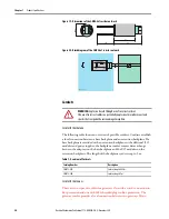
Testing physical 1718 Ex I/O unit connection
1.
Disconnect the bus connector from the master.
2.
Deactivate the terminator on the bus connector (bus start).
3.
Measure the voltage between A and B on the bus connection of each
1718 Ex I/O unit.
A voltage of U = 1.1 V must be present between A and B on each 1718
Ex I/O unit.
4.
Activate the terminator on the bus connector for the master.
5.
Plug the bus connector back into the master.
Configuration of an RS-485-Based Bus System
Configuration of the entire 1718 Ex I/O is conducted via the adapter.
Communication with the adapter can be set up via either the fieldbus or the
service bus.
Startup Phase
TIP
Perform the measurements from the control room.
TIP
Adapter FB8207* can be configured via the service bus only.
For more information, refer to the software manual for the adapter used.
IMPORTANT
Do not start to operate all the 1718 Ex I/O units simultaneously; instead,
connect each I/O unit to the master one after the other.
Ensure that the master read cycle and the
com unit watchdog
are
coordinated with one another. The duration for the transition to substitute
values must be longer than the duration of a bus cycle.
For the purposes of fault analysis, we recommend using a bus monitor that is
capable of passively monitoring data telegrams on the fieldbus.