


Rockwell Automation Publication 1718-UM001A-EN-E - December 2019
23
Chapter
2
Commissioning
This chapter describes the commissioning of the RS-485-based bus system.
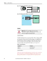
Testing physical connection right to the end of the segment
1.
Disconnect the bus connector from the master.
2.
Deactivate the terminator on the bus connector (bus start).
3.
Measure the voltage at the bus connector between A and B.
A voltage of U = 220 Ω / (220 Ω + 2 * 390 Ω) * 5 V = 1.1 V must be
present between A and B. This voltage is the result of the field-side
terminator. If the 1.1 V voltage is not present, there is either no
terminator connected at the end, the cable is faulty, or there is no
terminating voltage at the 1718 Ex I/O unit.
4.
Measure the current at the bus connector between A and B.
It must be possible to measure a current of I = 5 V / (2 * 390 Ω) ≈
6.4 mA between A and B. If the current is significantly higher, by a
factor of 2 or more, the bus is terminated using more than one
terminator. If the current is I ≈0 mA, then either there is no terminator
present, the cable is faulty, or there is no terminating voltage. In this case,
there should be a resistance of 220 Ω between A and B. Should neither
current nor resistance be present, the terminator is missing at the end of
the bus or the cable is faulty.
5.
Activate the terminator on the bus connector for the master.
6.
Plug the bus connector back into the master.
WARNING:
When taking measurements in explosion-hazardous areas, there
is an explosion hazard from sparks forming.
Use suitable measuring equipment or ensure there is no potentially
explosive atmosphere.
TIP
Perform the measurements from the control room.