background image

9

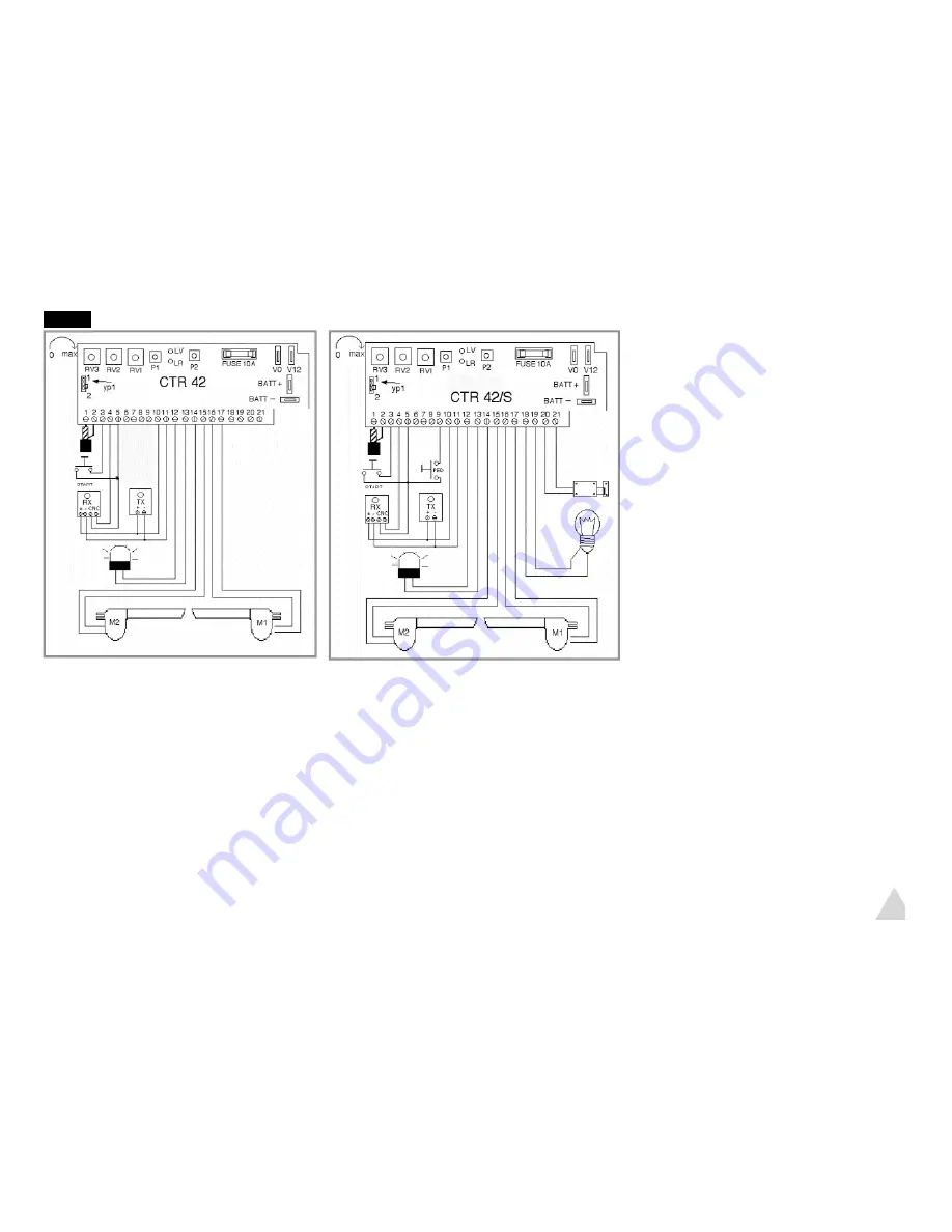
Fig.14

3.2  Special connections only for CTR42/S  Fig.14

Caution : only for the following references:
HC412.03/400 protop and 812.03/400 protop professional automation
CTR42/S programmer version
It will be possible to:
1. Connect an electric lockset
2. Another garden lights output
3. Open only one wing to allow the pedestrian crossing
How to proceed:
1. carry out all the connections, see paragraph 3.1 and possibly photocells paragraph 3.4.
2. Connect the terminals:
18-19 to a low voltage relay which is, on its turn, connected to garden lights
20-21 to a 12V electric lockset to be connected to the gate and which shall be activated at each movement
5-9 to a push-button that will activate the only pedestrian crossing.
Caution: giving a pulse on the button connected to terminals 5-9 NO (normally open) the wing will open corresponding to the first
motor M1.  Also in this case one can program the operation in step-to-step or automatic mode.

3.3 Settings 

Fig.14

1.Motor 1 RV1 trimmer and motor 2 RV2 trimmer ampere set-
ting or safety setting: it shall be set as to ensure safety in case
of obstacle, however with enough power to move wings. Turn
the trimmer clock-wise to increase the power.
Caution: during winter months or when a strong wind blows,
the settin

2.PROGRAM: RV3 trimmer allows to manage two operating
modes:
A: Step-to-Step, by setting the trimmer to “0” ZERO, by com-
pletely turning counter-clockwise (each step is controlled by a
single pulse)
B:Automatic with closing after a set time: to set the pause time
between opening and closing, turn the trimmer clockwise till
the desired time is set. (Warning: turn _ revolution at least)  
(During the opening and pause the equipment shall not accept
other signals, while during closing a pulse will reverse the
movement)
Caution: ALL THE SETTINGS SHALL BE PERFORMED WITH
THE WINGS CLOSED: in addition, they will be stored only at a
cycle start, therefore they shall be effective only starting from
the next cycle.

Summary of Contents for 412.03pro

Page 1: ...te 2 1 Front support assembly 2 2 Second actuator assembly 3 0 Wiring 3 1 Standard electric connections 3 2 Special connections 3 3 Settings 3 4 Special electric connections photocells 3 5 Emergency b...

Page 2: ...nel remote transmitters with 12V built in battery C No 1 Key selector D No 1 Unlocking key I No 1 Blinker E No 1 Pair of photocells M No 1 Antenna with cable N HC 812 03 400 protop max 3 x 2 m No 2 12...

Page 3: ...433 92 MHz radioreceiver in compliance with European norms I ETS 300 220 12 V AC power supply input 12 V DC outputs Double working program Step to step Automatic Amps safety control system Power supp...

Page 4: ...During the pause the system does not accept closing pulses During closing a pulse reverses the movement reopening The blinker E will warn the wings are moving The system is designed to last many years...

Page 5: ...e A measure is actually ininfluent in the choice therefore it can be determined only by the size of the pillar Some standard advised measures are for 300 mm stroke actuators Gates not exceeding 150 cm...

Page 6: ...gate with the rod COMPLETELY INSIDE position perfectly horizontal 3 Fit the H plate 4 Then fix the H plate to the gate by means of screws or by welding it to the gate It is advisable to check the goo...

Page 7: ...tor M2 Bipolar cable 1 5 mm_ cross section 3 Blinker connection cable not supplied 4 Key selector connection cable not supplied 5 Connector block not supplied Minimum height above ground 40 cm 6 Under...

Page 8: ...se photocells were not used connect terminals 4 5 with a jumper operations already carried out in the workshop 3 The green LED will go on TEST By pressing the T1 left hand button of the remote transmi...

Page 9: ...e can program the operation in step to step or automatic mode 3 3 Settings Fig 14 1 Motor 1 RV1 trimmer and motor 2 RV2 trimmer ampere set ting or safety setting it shall be set as to ensure safety in...

Page 10: ...g 16 In case photocells were more than ONE pair carry out connection SERIES Fig 16a Provide for a digging in the ground suitable to lay a cable duct crossing the gate width 1 Cable having a minimum cr...

Page 11: ...o use the remote transmitter at the same time The selector can operate the gate according to the set program The contact is Normally Open N O In case more than one selector or possibly a switch were t...

Page 12: ...in the programming ALL THE 12 CODES HAVE NECESSARILY TO BE ENTERED ALSO IN CASE OF ERROR DURING PROGRAMMING To carry out a new programming repeat the instruction from point 1 5 After having reached t...

Page 13: ...her Press the key of the chosen channel T1 T2 and T3 of the remote transmitter to transmit the code to the programmer Caution the receiver will accept a code that allows this further function only if...

Page 14: ...e parts Caution The gate automation is a device with a high technological content both for the high level of the software used and for the mechanical components manufactured to achieve a long lifetime...

Page 15: ...R39 Rotor provided with manifold and winding R71 R72 Plastic casing for electronic equipment with cover and 230 12V transformer R73 Fairleads CTR42 Programmer card CRT42 S Programmer card for professi...

Page 16: ...nding on the manufacturer 5 This guarantee neither influence the rights of the customers envisaged by law according to the national applicable laws nor the rights of the customer towards the reseller...

Reviews: