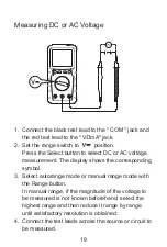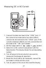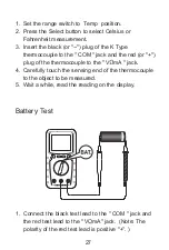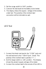
1. Connect the black test lead to the " COM " jack and
the red test lead to the " V mA" jack. (Note: The
polarity of the red test lead is positive "+". )
2. Set the range switch to LED position. The display
shows the present supply voltage of the meter.
3. Connect the red test lead to the anode of the LED to
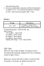
LED Test
2. Set the range switch to BAT. position.
3. Connect the test leads to the battery to be tested.
4. The display shows the approx. voltage of the battery
under test. The polarity of the red test lead
connection will be indicated as well.
28
Summary of Contents for EM3672
Page 1: ...Read this manual thoroughly before use 3672 Digital Multimeter Users Manual...
Page 2: ......
Page 36: ......

