background image

W 3 1   S E R I E S  
H I G H   P R E S S U R E   B R E A T H I N G   A I R   C O M P R E S S O R


©ALKIN Kompresör Sanayi ve Ticaret Limited Şirketi 

25


Electrical Panel: 

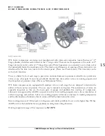
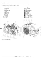
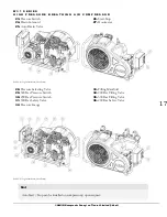
It is located at the front view / left section of the compressor. It accommodates all the electrical gear to start the 
motors and control the system. 


Pressure Switch: (

For Auto Drain Models

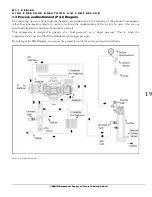
It  is  located  at  the  front  view  /  right  section  of  the  compressor.  This  switch  both  indicates  the  purifier 

pressure, and the set pressures on its dial, while serving as a double circuit pressure switch. It controls the 
start-stop operation of the compressor. The pressure-sensing end of the pressure switch is connected to a 

port  on  the  purifier;  when  the  pressure  inside  the  purifier  reaches  the  set  pressure,  it  cuts  off  the  control 
circuit, and stops the electric motor. (See the following section for further details.) 

 
Auto Drain Valves: (

For Auto Drain Models)


The automatic drain incorporates a small piston with high pressure in the bottom, and low pressure on top; 
the surface where low pressure acts on is larger than the surface where the high pressure effectively acts on 

the piston. Therefore the force on the top is larger and causes the piston to sit and seal the high-pressure vent 
port. The drain valves are controlled by a solenoid mounted on the pilot valve fitting. It receives compressed 

air from the 2nd stage air inlet and sends it over the 2 drain valves forcing them to close. When the solenoid 
is de-energized, it removes the control air over the top of the drain valve pistons, allowing the high pressure 

acting from the bottom of the pistons, to open and perform drain operation. 
 

Electric Motor: 

The compressor is driven by an electric motor and is belt driven. There is a hourmeter on the control panel. 


Intercoolers and Aftercooler:


These are the cooling tubes that cool  down the air getting warmed after compression in stages, which are 
located in interstages and at the discharge of the final stage of the compressor  


INTERCOOLERS  AND  AFTERCOOLER  ARE  NOT  NECESSARILY  REPLACED  UNLESS  A 

WEARING, CRACKING OR BREAKING OCCURS. 


Water Separators:


They remove the water condensate from the compressed air occurred in stages under pressure. There are two 

water separators on W31 Series; 2

nd 

and 3

rd

 Stgs. 


Purifier: 

This is the filtration system that purifies the compressed air to  produce breathing air comply with breathing air 

quality standards. Air compressed in the compressor stages finally enters the purifier. A refillable cartridge which 
contains the consumables performing the filtration is placed in the purifier housing. Refillable cartridges are more 

Summary of Contents for W31 series

Page 1: ...W31 SERIES...

Page 2: ...W 3 1 S E R I E S H I G H P R E S S U R E B R E A T H I N G A I R C O M P R E S S O R ALKIN Kompres r Sanayi ve Ticaret Limited irketi 2...

Page 3: ...InstructionsManual and Parts List...

Page 4: ......

Page 5: ...e copied by any means or used for any other purposes other than servicing ALKIN W31 Series compressors unless specific written permission of ALKIN is received ALKIN KOMPRES R San ve Tic Ltd ti brahim...

Page 6: ...W 3 1 S E R I E S H I G H P R E S S U R E B R E A T H I N G A I R C O M P R E S S O R ALKIN Kompres r Sanayi ve Ticaret Limited irketi 6...

Page 7: ...Components System 24 1 7 Description of Controls 26 1 7 1 Manual Start 26 1 7 2 Auto Stop 26 1 7 3 Auto Drain 26 1 8 Installation 26 1 8 1 Inspection 26 1 8 2 Location 27 1 8 3 Piping 27 1 9 4 Electri...

Page 8: ...placement 42 2 5 15 Auto Drain Valve Adjustment with Repair Kit 42 2 5 16 Oil Change Instructions 43 2 5 17 Valve Replace Instructions 43 2 6 Abrasion Limits 44 3 0 TROUBLESHOOTING 45 4 0 PARTS LIST 4...

Page 9: ...cting rods high efficiency valves which all add to the superior and lasting performance of the ALKIN compressors Your compressor is backed up with worldwide sales and service organization ready to acc...

Page 10: ...W 3 1 S E R I E S H I G H P R E S S U R E B R E A T H I N G A I R C O M P R E S S O R ALKIN Kompres r Sanayi ve Ticaret Limited irketi 10...

Page 11: ...is safe to do so Do not operate it with known unsafe condition Tag the compressor and render it inoperative by disconnecting the power supply so that others who may not know of the unsafe condition wi...

Page 12: ...live electrical parts such as terminals to avoid arcing which might serve as a source of ignition Keep a suitable BC or ABC fire extinguisher s nearby while servicing and operating the compressor Keep...

Page 13: ...electrical system 1 1 9 Lifting and Carrying If you must lift the compressor lift in full compliance with codes and regulations Make sure entire lifting rigging and supporting structure has been insp...

Page 14: ...essors Working pressure of these compressors depending on valves and heads can be between 10 bar 1500 psi and 350 bar 5000 psi Do not attempt to modify compressor to operate at higher pressure without...

Page 15: ...oblem in valves or any other parts It must be periodically checked that these safety valves are working properly and they keep their set pressure values Please see Maintenance Table W31 Series compres...

Page 16: ...pressor Unit 2 Electric Drive 3 Subbase 4 Water Separator 5 Purifier 6 Priority Valve 7 Check Valve 8 Aftercooler 9 Safety Valve 10 Intake Filter 11 Filling Hose 12 Filling Valve 13 Filling Gage 14 Yo...

Page 17: ...alve 26 Start Stop 27 Hourmeter ekil 4 W31 general layout Auto Drain 28 Pressure Selecting Valve 29 300 Bar Pressure Switch 30 200 Bar Pressure Switch 31 300 Bar Safety Valve 32 Pressure Gauge 33 Fill...

Page 18: ...Outlets Working Pressure Purifier W31 Mariner Breathing Air Compressor 2 2 kw 1 200 300 Bar P21 Performance Data Model Working Pressure FAD Motor Power RPM Cylinder Diameter No of Stages BAR PSI Lt m...

Page 19: ...al components rather than pneumatic symbols in order to facilitate the understanding of the system by users who are not specifically trained to understand pneumatic symbols This compressor is designed...

Page 20: ...W 3 1 S E R I E S H I G H P R E S S U R E B R E A T H I N G A I R C O M P R E S S O R ALKIN Kompres r Sanayi ve Ticaret Limited irketi 20 ekil 7 P I Diagram Auto Drain...

Page 21: ...W 3 1 S E R I E S H I G H P R E S S U R E B R E A T H I N G A I R C O M P R E S S O R ALKIN Kompres r Sanayi ve Ticaret Limited irketi 21 ekil 8 P I Diagram Dual Pressure...

Page 22: ...air temperatures allowing the water vapor to condensate and settle in the bottom sections of the water separators The water separator and the oil water separator prefilter are equipped with either a m...

Page 23: ...LER OR ALKIN FOR REPLACEMENT OR MAINTENANCE Connecting Rods In W31 Series compressors there are three connecting rods two of which are the same and the third one is with a stick at the bottom part ser...

Page 24: ...T OR MAINTENANCE Safety Valves Safety valves are found at the end of each stage of compressor unit All the safety valves are subject to pressure tests and working pressure are set accordingly Therefor...

Page 25: ...l the high pressure vent port The drain valves are controlled by a solenoid mounted on the pilot valve fitting It receives compressed air from the 2nd stage air inlet and sends it over the 2 drain val...

Page 26: ...pressing the start stop button on the control panel 1 7 2 Auto Stop If the W31 Mariner is installed with a Pressure Switch the compressor stops when pressure reaches to the stop pressure set on the p...

Page 27: ...nd the filling panel or fill station depending on the length between the compressor and the filling panel properly selected stainless steel pipes must be used The piping should be installed in full co...

Page 28: ...r will not be working for a long time for any reason and stored idle during this time it is suggested to do the following steps before putting it out of reach in order to keep it in good condition 1 D...

Page 29: ...n normal service Not IF THE COMPRESSOR HAS BEEN STORED WITH THE OLD OIL INSIDE FIRST RUN THE COMPRESSOR FOR A WHILE AND STOP IT AFTER THE OIL IS WARMED UP DISCHARGE THE OLD OIL AND REFILL WITH NEW OIL...

Page 30: ...after you make sure that you drain the old oil completely in the crankcase Refill the oil every 6 months unless you reach the replacement time of the oil stated in the Maintenance Table 1 11 3 Extreme...

Page 31: ...original settings Only authorized service technicians are certified to make such adjustments If required replace and return the old one for reconditioning to the manufacturer or to a dealer nearest y...

Page 32: ...the filling hose is automatically released by the filling valve when the filling valve is closed Disconnect the cylinder 300 Bar Cylinder Filling Instruction Set the pressure selection valve to 200 Ba...

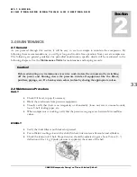
Page 33: ...sor by switching off the power and blowing down the pressure inside all equipment like the filters purifiers pipings etc If a bank system exists isolate by closing the appropriate valves 2 2 Maintenan...

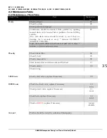
Page 34: ...e purifier cartridge Tighten all screws and nuts Use reasonable force If you are unsure use torque wrench Check valves and verify that there is no accumulation of carbon or dust on them ANNUAL MAINTEN...

Page 35: ...k to see if they are draining for 6 seconds at every 7 minutes CONSULT ALKIN IF UNSURE 03 Open the manual drains beneath water separator s at every 7 minutes to drain condensate water Weekly Check int...

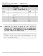
Page 36: ...ce 14 500 Hrs 1 Calibrate auto drain valves with auto drain maintenance kit For auto drain models 1 set 15 1000 Hrs 1 Ring 1 set 17 2 Valve 1 set 3 Gasket Set 1 set 4 O ring Set 1 set Important COMPRE...

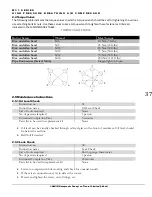
Page 37: ...d allen head M16 200 Nm 141 ft lbs Pipe Connectors Swivel Nuts Finger tight 1 2turn 2 5 Maintenance Instructions 2 5 1 Oil Level Check Instruction no 01 Instruction name Oil Level Check List of tools...

Page 38: ...Completion Time 5 minutes Parts list to be used in replacement kit None Check intake filter element at every 50 running hours and clean with pressurized air from inside towards outside Depending on am...

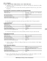
Page 39: ...Check List of tools required Amperemeter No of persons required 1 person Estimated Completion Time 5 minutes Parts list to be used in replacement kit None Check with an amperemeter at max load for co...

Page 40: ...persons required 1 person Estimated Completion Time 10 minutes Parts list to be used in replacement kit None If check valve is leaking remove it with appropriate tool Clean its place and install the...

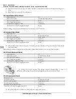
Page 41: ...ywheel and install new ones Rotate flywheel by hand to check tension Reconnect flywheel grid with appropriate tools Start the compressor and check the proper rotation 2 5 13 Purifier Cartridge Refill...

Page 42: ...pair Kit List of tools required No of persons required 1 person Estimated Completion Time Parts list to be used in replacement Stop the compressor Verify complete depressurization of pressure equipmen...

Page 43: ...or Valves After roughly half an hour s operation valves should be checked Note that intake line to valve heads should be hand warm and outlet piping should be hot Should the intake pipe to the valve h...

Page 44: ...lves could work loose due to settings of the gaskets Remove and check the valves every 1000 operating hours Replace the valves every 2000 operating hours to avoid fatigue failure 2 6 Abrasion Limits C...

Page 45: ...new gasket and reassemble Deflected crankshaft or crankshaft bearing failure Replace the crankshaft Excessive dirt or carbon on piston s Remove the compressor air heads clean pistons and valve s or re...

Page 46: ...Replace its spring and disc 3 9 INSUFFICIENT AIR AT THE POINT OF USE Leaks or restrictions Check for leaks and restrictions in the piping and hoses Restricted air intake Replace the intake filter ele...

Page 47: ...ed air intake Replace the intake filter element Blown cylinder gasket Install a new gasket Worn or broken valves Replace valves Air leaks in the system Check for leaks fix the problem Loose belts Adju...

Page 48: ...mely dirty ambient conditions Pipe the intake filter to a cleaner location if possible alternatively use a heavy duty two stage filter 3 21 ODOR IN DISCHARGED AIR Purifier cartridge saturated Replace...

Page 49: ...W 3 1 S E R I E S H I G H P R E S S U R E B R E A T H I N G A I R C O M P R E S S O R ALKIN Kompres r Sanayi ve Ticaret Limited irketi 49 4 0 Parts List PartsList Section 4...

Page 50: ...W 3 1 S E R I E S H I G H P R E S S U R E B R E A T H I N G A I R C O M P R E S S O R ALKIN Kompres r Sanayi ve Ticaret Limited irketi 50...

Page 51: ...23 Elbow 1 4x 8 plastik 1 9 3002 27 Hub 1 10 3002 88 Gasket 1 11 7869 01 DIN 472 62 ring 1 12 3002 86 Spacer 1 13 3002 25 Bearing 1 14 7000 09 Crankshaft 1 15 3004 47 Rod 3rd stage 1 16 3004 46 Rod 2n...

Page 52: ...71 01 Cylinder 1st stage 1 7 3002 75 Nut M6 4 8 7091 08 Washer M6 4 9 AYD 54 Gasket 1 10 AYD 30 Complete valve 1st stage 1 11 AYD 55 Gasket 1 12 AYD 27 Cylinder cover 1st stage 1 13 3001 46 Filter ele...

Page 53: ...4 8 7091 08 Washer M6 5 9 3002 67 Gasket 1 10 6897 04 Complette valve 2nd stage 1 11 3004 72 O ring 2ng stage valve 2 12 AYD 28 Cylinder cover 2nd stage 1 13 ayd 101 O ring 27 50x1 78 3 14 3003 56 Cov...

Page 54: ...stage 1 9 7010 01 Compression ring 3rd stage 7 10 7729 20 O ring 21 95x1 78 1 11 6841 01 Cylinder 3rd stage 1 12 7729 21 O ring 25 12x1 78 1 13 3002 68 Gasket Guide cylinder 1 14 6842 01 Cylinder 3rd...

Page 55: ...7084 02 Elbow 1 4 1 4 2 5 7424 01 Nipple 1 4 x 12 2 6 2000 13 Tube 3rd Stg Water Seperator 1 7 7422 01 Nipple 1 4 x 6 3 8 7933 17 Safety Valve 110 Bar 2 9 7084 03 Elbow 1 10 7020 00 Drain Valve 3 11...

Page 56: ...2000 12 3rd Stage Inlet Tube 1 8 2000 15 Intermediate Tube 1 9 7424 01 Nipple 1 4 x 12 2 10 7084 02 Elbow 1 4 1 4 3 11 7422 01 Nipple 1 4 x 6 4 12 7084 10 Tee 1 4x1 4 1 13 7078 03 Nipple 1 4x1 8 1 14...

Page 57: ...C O M P R E S S O R ALKIN Kompres r Sanayi ve Ticaret Limited irketi 57 4 7 Aftercooler No Par a no A klama Adet 1 7091 65 Clamp 2 2 7091 66 Clamp 2 3 6908 19 Aftercooler tube 1 4 7867 45 Bolt DIN 93...

Page 58: ...1 7663 02 Cover 1 1 2 6893 06 O ring 2 1 3 7983 01 Filter element 1 1 4 7765 06 Filter element 1 1 5 7765 08 Washer 1 1 6 6882 18 Screw 1 1 7 7663 08 Body 1 1 8 6916 05 Diffuser 1 1 9 7663 09 Top cove...

Page 59: ...55 Bolt M6x25 1 8 7038 04 Yoke holder 1 9 7867 09 Bolt M6x20 2 10 7091 28 Spring washer M6 6 11 7091 17 Washer M6 9 12 6882 18 Bolt 5 13 Electric Motor 1 13 1 80081 06 2 2kw 3000d d 220V 13 2 80081 1...

Page 60: ...Washer M6 5 5 7091 28 Spring Washer M6 2 6 7867 09 Bolt M6x20 1 7 7953 45 V Belt 1 8 7976 07 Pulley 1 9 7867 98 Bolt M8x40 4 10 80058 00 Petrol Engine 1 11 3002 09 Crankcase Lower Plate 1 12 6914 60 C...

Page 61: ...irketi 61 4 11 Filling line Standart No Part nr Description Qty 1 7890 01 Nipple Hose 1 2 7670 13 O ring Hortum 2 3 7912 12 Filling hose 1 4 7235 22 Pressure gauge 400 Bar 1 5 7866 00 Filling valve 1...

Page 62: ...lling line Optional Dual output No Part nr Description Qty 1 7084 03 Tee 1 4x1 4 1 2 7890 01 Nipple Hose 2 3 7670 13 O ring Hose 4 4 7912 12 Fillig hose 2 5 7866 00 Filling valve 2 6 7235 22 Pressure...

Page 63: ...4 1 6 7191 04 Routing valve 1 4 500 bar 1 7 3004 70 Tube ass y 1 8 7084 03 Tee 1 4x1 4 1 9 3003 86 Filling collector 1 10 7083 02 Plug 3 11 7078 41 Nipple 1 4NPTx1 4BSP 3 12 80071 01 Pressure switch...

Page 64: ...W 3 1 S E R I E S H I G H P R E S S U R E B R E A T H I N G A I R C O M P R E S S O R ALKIN Kompres r Sanayi ve Ticaret Limited irketi 64...

Page 65: ...W 3 1 S E R I E S H I G H P R E S S U R E B R E A T H I N G A I R C O M P R E S S O R ALKIN Kompres r Sanayi ve Ticaret Limited irketi 65 5 0 Tecnical drawings Teknical Drawings Section 5...

Page 66: ...W 3 1 S E R I E S H I G H P R E S S U R E B R E A T H I N G A I R C O M P R E S S O R ALKIN Kompres r Sanayi ve Ticaret Limited irketi 66...

Page 67: ...W 3 1 S E R I E S H I G H P R E S S U R E B R E A T H I N G A I R C O M P R E S S O R ALKIN Kompres r Sanayi ve Ticaret Limited irketi 67...

Page 68: ...W 3 1 S E R I E S H I G H P R E S S U R E B R E A T H I N G A I R C O M P R E S S O R ALKIN Kompres r Sanayi ve Ticaret Limited irketi 68...

Page 69: ...W 3 1 S E R I E S H I G H P R E S S U R E B R E A T H I N G A I R C O M P R E S S O R ALKIN Kompres r Sanayi ve Ticaret Limited irketi 69...

Page 70: ...W 3 1 S E R I E S H I G H P R E S S U R E B R E A T H I N G A I R C O M P R E S S O R ALKIN Kompres r Sanayi ve Ticaret Limited irketi 70...

Page 71: ...W 3 1 S E R I E S H I G H P R E S S U R E B R E A T H I N G A I R C O M P R E S S O R ALKIN Kompres r Sanayi ve Ticaret Limited irketi 71...

Page 72: ...W 3 1 S E R I E S H I G H P R E S S U R E B R E A T H I N G A I R C O M P R E S S O R ALKIN Kompres r Sanayi ve Ticaret Limited irketi 72...

Page 73: ...W 3 1 S E R I E S H I G H P R E S S U R E B R E A T H I N G A I R C O M P R E S S O R ALKIN Kompres r Sanayi ve Ticaret Limited irketi 73...

Page 74: ...W 3 1 S E R I E S H I G H P R E S S U R E B R E A T H I N G A I R C O M P R E S S O R ALKIN Kompres r Sanayi ve Ticaret Limited irketi 74...

Page 75: ...R E B R E A T H I N G A I R C O M P R E S S O R ALKIN Kompres r Sanayi ve Ticaret Limited irketi 75 ALKIN KOMPRES R SAN Ve Tic Ltd ti brahim Turan Caddesi No 127 Menderes zmir Tel 90 232 782 2290 Fax...

Reviews: