


7
www.observint.com
© 2020 Observint Technologies. All rights reserved.
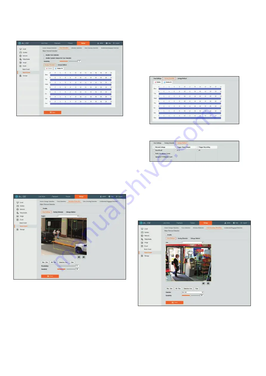
Face Detection Smart Event setup
The Face Detection Smart Event detects faces anywhere in the video stream. This feature is configured
very similar to the Scene Change Smart Event. Refer to the instructions in that sub-step for more
information.
Face detection provides two modes for detecting faces:
—
Face detection
: Enable Face detection event reporting.
—
Dynamic Analysis for Face Detection
: Mark faces detected in Live View video image
with a green rectangle.
Intrusion Detection Smart Event setup
Intrusion detection feature detects objects which enter and loiter in a pre-defined virtual region. This
feature can be used to create a detection region where the an event is triggered when the object in the
region is larger then a minimum size and smaller than a maximum size and remains there for at least
a preset time. This event can trigger actions performed by the camera to report and record the alarm
information.
1.
Open the
Intrusion Detection
settings menu.
Go to
Setup | Event | Smart Event | Intrusion Detection
2.
Check the
Enable
select box to enable the feature.
3.
Select the region number from the drop-down to select the detection area you want to
configure. You can configure up to four (4) regions.
4.
To create a detection region where an alarm is triggered when a percentage of the region is filled:
a.
Click the
Detection Area
button.
b.
Click a point on the screen to set one corner of the detection region, and then click three
more points in a circular fashion to set three other corners of the detection region. A
quadrilateral will appear that is tinted yellow. See above.
5.
Set the maximum and minimum size of objects to detect:
a.
Click the
Max. Size
button, and then drag a rectangle across the video image to represent
the maximum size of objects to detect. The rectangle will be labeled with
Max
.
b.
Click the Min. Size button, and then drag a rectangle across the video image to represent
the minimum size of objects to detect. The rectangle will be labeled with
Min
.
c.
Set the following options:
Threshold
: Range [0-10]s, the threshold for the time of the object loitering in the region.
If you set the value as 0, alarm is triggered immediately after the object entering the
region.
Sensitivity
: Range [1-100]. The value of the sensitivity defines the size of the object
which can trigger the alarm. When the sensitivity is high, a very small object can trigger
the alarm.
6.
Click the
Save
button to retain your settings.
7.
Click the
Arming Schedule
tab. To configure the schedule, refer to “Scene Change Detection
Smart Event setup” on page 6.
8.
Click the
Linkage Method
tab. To configure the Linkage Methods menu, check the select boxes
for the actions you want the camera to perform when the event occurs.
9.
Click the
Save
button to retain your settings.
Line Crossing Detection Smart Event setup
Line crossing detection feature detects objects which cross a pre-defined virtual line. You can configure
the minimum (
Min
) and maximum (
Max
) size of the object that crosses the line, and position the line
anywhere and at any angle in video stream. Also you can detect when the object crosses the line from
just one direction or the other direction, or detect when it crosses from either direction. This alarm can
trigger actions performed by the camera to report and record the alarm information.
1.
Open the
Line Crossing Detection
settings menu.
Go to
Setup | Event | Smart Event | Line Crossing Detection
2.
Check the
Enable
select box to enable the feature.
3.
Select a
Line
number from the drop-down. You can configure up to four (4) lines.
4.
To setup a line:
a.
Click the
Detection Area
button. A virtual line will appear on the video image.
b.
Drag the ends of the line to change the angle, and drag the body of the line to change the
position in the video.
5.
Set the maximum and minimum size of objects to detect:


