


1
www.observint.com
ALI-NS2036R-RBI_CQ
200218
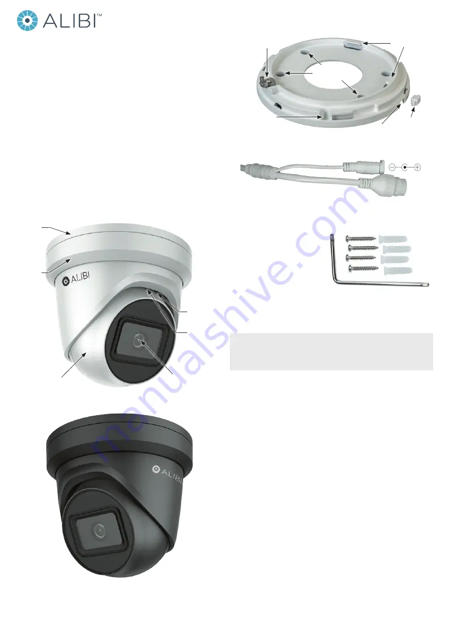
Fixing screw
and tab
Cable channel
plug
Tabs to hold
turret assembly
Cable channel
Holes for surface
mounting screws (3)
Holes for bracket
mounting screws
Adapter plate
Ethernet RJ-45 (with PoE)
12 Vdc connector with plug
Drop cable connectors
What’s in the box
Your camera includes the items shown below:
•
Security L-wrench
•
Mounting hardware - four screws and
wall inserts
•
Drill template
•
Waterproof Ethernet Fitting
•
Installation and setup instructions
Step 1. Route wiring to the camera
Interface cables can be routed into the camera either through the adapter plate (through the mounting
surface) or through the cable channel on the side of the camera.
NOTE
When selecting a mounting location for the camera
• Make sure that there are no reflective surfaces near to the camera lens. Light from the camera may
bounce back onto the lens causing reflections.
• Determine how interface wiring are routed into the camera. The cable can be routed through the
mounting surface and access hole in the mounting plate or through the side inlet.
The camera includes connectors for the following:
•
Ethernet
(required): The Ethernet drop cable can connect to a LAN extension cable from a
switch or Network Video Recorder. The camera can be powered across the LAN using power
over Ethernet (PoE) injection. See the
Specifications
section at the end of this document for
power requirements. A weatherproof Ethernet Fitting is provided.
•
12 Vdc power input
(optional if PoE powered, required if not): If powering the camera
with a long power extension cable, refer to the tables at the end of this guide for wire gauge
requirements. Voltage input at the camera can be within the range 12 Vdc ± 25%.
1.
Route a LAN extension cable from a network switch or Network Video Recorder to where the
camera will be installed.
2.
If the camera is not powered using PoE, route 12 Vdc power cables from an adequate power
source to the location where the camera will be installed. Voltage input at the camera can be
within the range 12 Vdc ± 25%.
Step 2. Remove the Adapter plate
To remove the adapter plate:
1.
Set the camera base down on a clean surface.
ALI-NS2036R, ALI-NS2036RB 6MP STARLIGHT
IP Turret Camera Quick Installation Guide
This document guides you through the basic steps to install and configure the ALI-NS2036R (white)
and ALI-NS2036RB (black) network turret cameras. These two cameras are identical except for the color.
These cameras features:
•
3072 x 2048 @ 20 fps (6MP) resolution
•
Color: 0.008 Lux @ (F1.2, AGC ON), 0.016 Lux @ (F1.6, AGC ON) minimum illumination
•
Up to 120’ IR
•
Starlight Low Light 0.008 Lux with 120 dB Wide Dynamic Range
•
2.8 mm fixed lens with 99° horizontal FOV
•
H.265+/H.265/H.264+/H.264 video compression
•
12Vdc & PoE (802.3af, class3) powering options
•
Built-in microSD/SDHC/SDXC slot, up to 128GB maximum capacity
•
IP67 weather-rated with -22°F ~140°F operating temperatures
•
Optional ALI-AB6 Alibi wall mount bracket with flange, ALI-AJ14 junction box
For more information, refer to these documents - available from your equipment vendor:
•
ALIBI™ Witness 2.0 App for Android or iOS Quick Start Guide
•
ALIBI™ IP Camera Firmware Version 5.4 User Manual
(or later) provided at:
AlibiSecurity.com/resources
Trim
ring
Lens
Shroud
and turret
assembly
Turret “UP”
orientation
MicroSD
card slot
and Reset*
Adapter
plate
ALI-NS2036R Camera assembly
ALI-NS2036RB Camera assembly


