


7
www.observint.com
© 2018 Observint Technologies. All rights reserved.
3.
Adjust the Brightness Contrast, Saturation and Sharpness of the image. Each parameter can be set to
a level of 0 ~ 100 either by moving the slider or entering the value in the box on the right. The effect
of the adjustment will appear in the Live View image in the menu.
Refer to the firmware user manual for your camera to use the other submenus on this screen.
For cameras connected directly to an NVR
1.
Log into the NVR with administrative privileges.
2.
Open the firmware Image menu. Go to
Menu | Camera Management | Image
3.
In the
Camera
field drop down list, select the camera you want to configure. In the example above,
[D1]IPCamera 01
is selected.
4.
Drag the
Brightness
,
Contrast
,
Saturation
and
Hue
adjustment markers left or right to perfect
the image from the camera. For some adjustments, you can click the up (
5
)or down (
6
)icons
near the adjustment value (on the right side) to incrementally change the value of those adjustment.
5.
Click
Apply
to save your settings for this camera.
Refer to the firmware user manual for your NVR to use the other submenus on this screen.
Capture Record Zoom
Live View image
NOTE
You can also observe video from the camera by plugging the Video Test Monitor cable into the CVBS
monitor connector in the camera, then attaching it to a spot monitor.
Step 9. License Plate Recognition
You can use the client software and a web browser to compose a rule to capture pictures configure the
camera to identify the license plant number. Gate traffic surveillance is used in the example shown here.
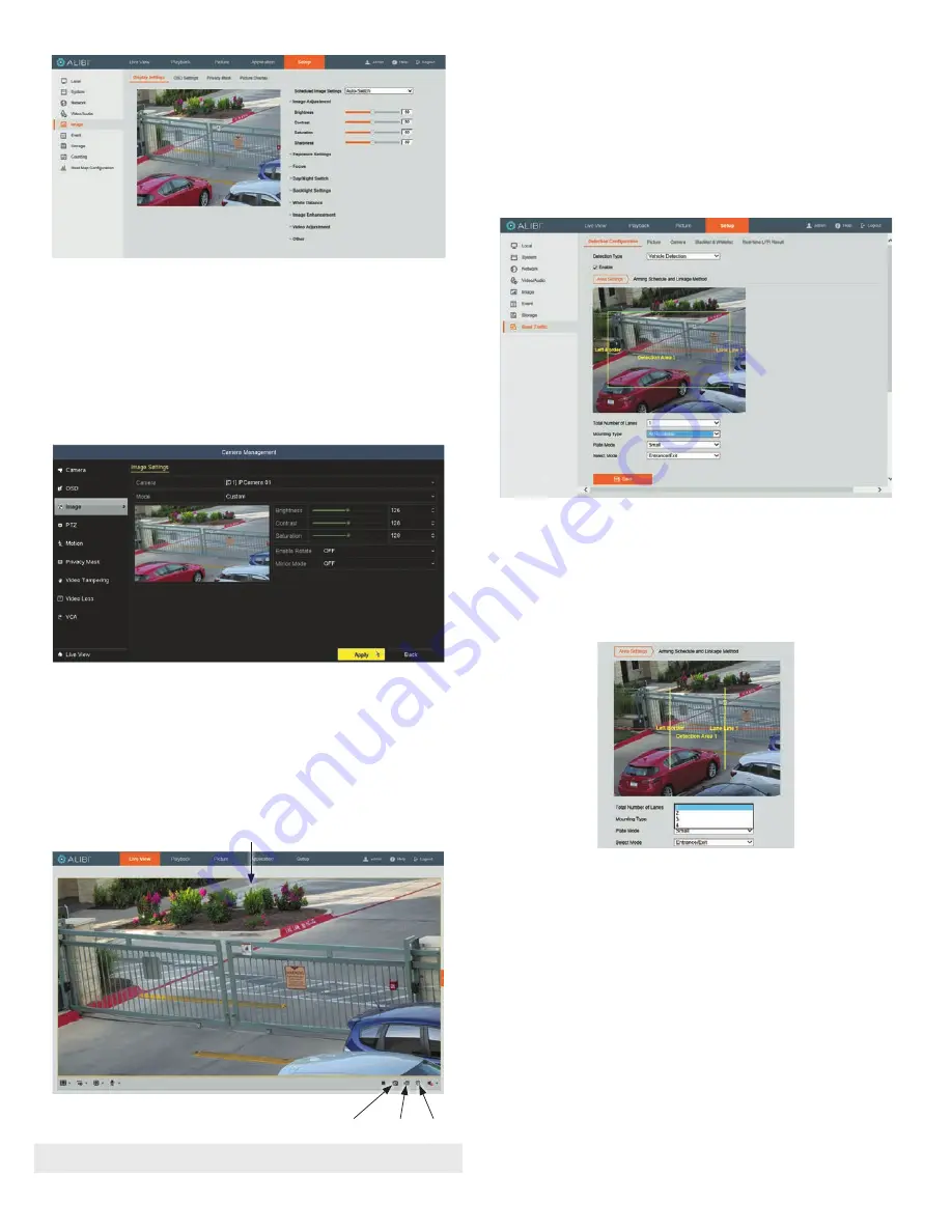
Enable Vehicle Detection
1.
Log into the camera via web browser.
2.
Go to the
Setup | Road Traffic | Detection Configuration
tab.
3.
Select
Vehicle Detection
and check the
Enable
select box. See above.
Select the detection area.
4.
In the menu shown above:
a.
Open the
Total Number of Lanes
drop down list, and select the appropriate value. In this
example, 1 lane was selected.
b.
Open the
Mounting Type
drop down list, and select the appropriate value. In this example,
At Roadside
was selected.
c.
Open the
Plate Mode
drop down list, and select either
Small
or
Large
.
d.
Open the Mode drop down list, and select the appropriate option.
5.
Click and drag the lane line to set the range, and then drag the line to adjust the length and angle.
a.
Click on the
Left Border
line, and then drag the dots at the ends of the line to set the left
border of the detection area.
b.
Repeat the previous sub-step with Lane Line(s).


