


4
www.observint.com
© 2018 Observint Technologies. All rights reserved.
Step 3. Activate Inactive Alibi device
NOTE:
If the camera LAN extension cable is attached to a Network Video Recorder (NVR), skip this step.
Refer to the documentation available for your NVR firmware for the procedure to activate the camera, if
necessary.
When an Alibi device is first installed, or reset to its factory configuration, it must be “Activated” before it
can be used. In the Alibi Configuration Tool, “Inactive” devices have a
Security
status of
Inactive
, and
an IPv4 address of
192.168.1.64
. A device is “Activated” when a password is assigned to the
admin
username of the device.
In the example below, an ALI-NS3022ANPR camera is activated and configured for its network. The
procedure is similar for all other Alibi network cameras currently available.
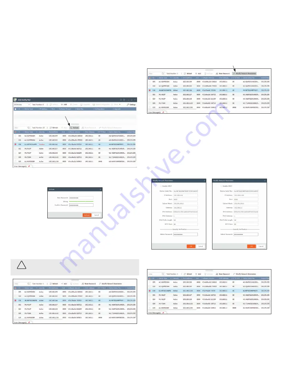
1.
Scan through the list of devices the Alibi Config Tool discovered for the Inactive device you want to
activate (see below). Click on the device in the list to highlight it, and then click the select box to
check it. See below.
Activate
2.
Click the
Activate
button. In the Activate window, you will create a password for the
admin
(administrator) username.
a.
In the Activate window, enter an a password for
admin
in the
New Password
field. Include a
combination of uppercase, lowercase alphabetic characters and numbers to create a “Strong”
password. The rating is shown beneath the field. See above.
b.
Enter the
admin
password again in the
Confirm
field, and then click
Activate
. In the screen
below, notice that the device Security status shows “Active”. Record your
admin
password for
reference later.
CAUTION
If you lose your
admin
(administrator) password, you cannot configure the device or restore
it to its factory settings. To reset your password,
call
your support organization for specific
instructions.
Notice that although the device is now activated, it retained the default IP address.
Step 4. Modify Network Parameters
NOTE:
If the camera LAN extension cable is attached to a Network Video Recorder (NVR), skip this step.
The camera will receive network configuration settings from the NVR. Refer to the documentation available
for your NVR firmware for more information.
You can change the network parameters of devices that are active.
1.
In the list of devices discovered, click on the device you want to change the network settings for, and
then click the select box to check it. See below.
Modify Network Parameters
2.
In the popup window, edit the current network parameters, and then enter the
admin
user
password in the field at the bottom.
a.
Enable DHCP
: You can select
Enable DHCP
to acquire compatible network settings from
a DHCP server installed on the LAN. However, these settings can be changed by the DHCP
server. Since it is recommended to use an unchanging IP address, you can use DHCP to acquire
compatible network settings, and then uncheck
Enable DHCP
and save that configuration to
retain the new network parameters.
b.
In the example below, the IPv4 address was changed to 192.168.3.100, and the IPv4 Gateway
was changed to 192.168.3.1. These settings were determined to be compatible with the
network router and other devices that share the same router.
3.
Click
OK
to save your settings. The parameter change(s) will be shown device’s network parameters
(see below).
Step 5. Login to the camera
NOTE:
If the camera LAN extension cable is attached to a Network Video Recorder (NVR), skip this step.
Microsoft® IE is used to access your camera remotely. IE must run as an Administrator to use all features
available through a remote login to the camera.


