Aliaro reserve the right to vary from the description given in this data sheet and shall not be liable for any errors.
www.aliaro.com
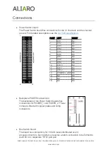
Connections
•
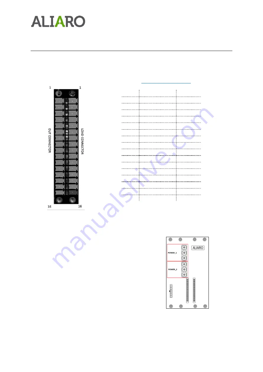
Power Switch board:
The Power Switch board has connections for the 12 channels and the channel
ground. For detailed descriptions see the
•
Backplane POWER connections:
The backplane of the Power Switch boards has
connections for POWER_1 and POWER_2. These
come pre-fitted with copper plates and crimp
connectors.
•
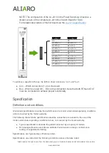
Bus Switch board:
The board has connections for 16 CAN-buses distributed over 4
groups/connectors. Each CAN-bus requires a return connection to be formed to
each ECU on respective “RTN” port pair.
PORT
LEFT
RIGHT
1
CH 1
NC
2
CH 2
NC
3
CH 3
NC
4
CH 4
NC
5
CH 5
NC
6
CH 6
NC
7
CH 7
NC
8
CH 8
NC
9
CH 9
NC
10
CH 10
NC
11
CH 11
NC
12
CH 12
NC
13
CHANNEL_GND
NC
14
NC
NC
15
NC
NC
16
NC
NC

