


alfasolar GmbH
Ahrensburger Str. 4 6, 30659 Hannover
Geschäftsführer:
Dipl.-Ing. M. Denz (CEO) / Dipl.-Kfm. K.-W. Hoffmann (CFO)
Amtsgericht Hannover HRB 544 55
Gerichtsstand und Sitz: Hannover
Seite 16 von 29
Tel:
Fax:
Mail:
Web:
+49 (0) 511-261 447-0
+49 (0) 511-261 447-50
[email protected]
www.alfasolar.de
Revision-Index:
Issued:
Doc.-Nr.
08
2012-12-13
ALE-IEC-01
3.4.8
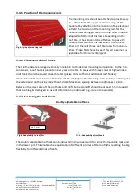
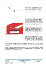
Arrangement of mounting rails on the fastening points and screwing them
down
Start with the alignment of the lowermost rail and the right or left edge. Then arrange the
additional rails. Important! The side ends (left or right) must be arranged so that they form a
vertical line running at an exact 90
angle to the lowermost rail. Otherwise the seams in the
module array cannot be properly aligned within these lines. The rails are then placed on the
roof hooks.
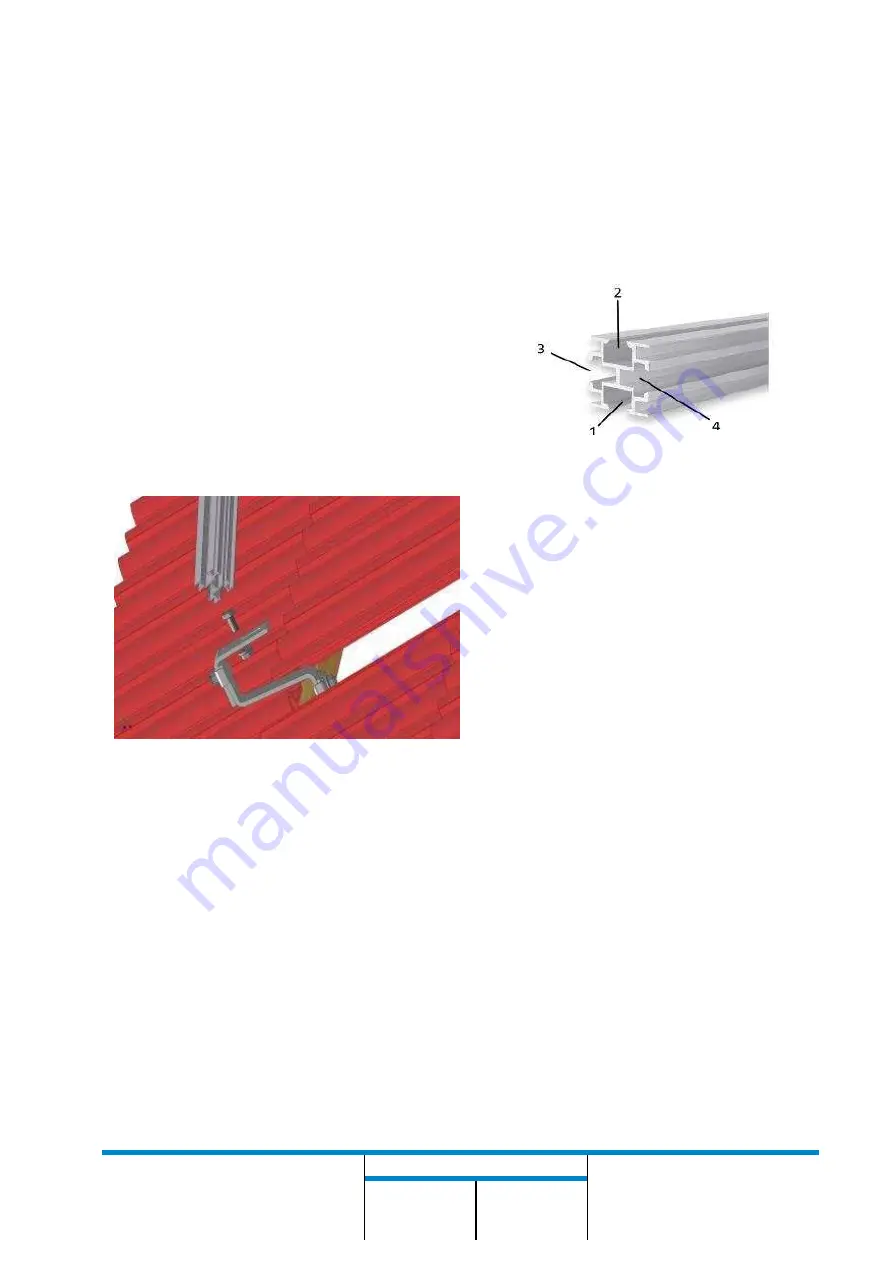
Please make sure that the center bar of the
rail is vertical for optimal stability of the sys-
tem and the large grooves face the bottom
(for connecting the roof hooks) and top
(for fastening the module).
Fig. 9: introduce the A2 profile into the clamping screw
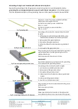
The bolts for fastening the roof hooks are
inserted into the bottom groove of the rail,
positioned and then screwed to the roof
hook using a serrated lock nut. The rails can
be extended with the rail connector if nec-
essary. In this case, insert the connecting
plate into the lateral groove and secure it
with 2 round-head screws M8x16 and
washers using the 5 mm hex key. For rails
longer than 2 m the variant listed in the
parts list can be used, since it ensures
greater stability.
3.4.9
Tightening and checking all screws of the substructure
To avoid damaging the threads, retighten each screw approximately a quarter turn upon en-
countering firm resistance. Important: Screws with damaged threads are difficult to loosen
P
I
G
T
easier to perform before the module is installed.
WARNI NG
:
Due to thermal extension of the mounting rails stress is caused to the modules. To avoid this
you should install an expansion gap of 20 mm after two rails length (12 m).
Fastening the modules
Fastening linking plate
Fastening the roof hooks
Cable channel
Fig. 8: A2-Mounting rail with channels


