


10
This opening must be made at the external wall of the room, that is, the room where the stove is located.
Intake, that is, supply of air for combustion from the garage, the depository for burning materials or from
the room where there is risk of fire is forbidden.
The hole, that is, the opening of the external suction air for combustion
must not be connected
by means of
pipe. If the room has some other equipment for heating, the suctions for air for combustion must provide
the amount of air which is necessary for proper operation of all devices.
Figure 8
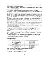
MINIMAL DISTANCES FOR PLACEMENT OF THE VENTILATION GRATE:
For proper and safe placement of the ventilation grate look at the data given in table 4. These are minimal distances
from every air space or smoke exhaust. This value can change the configuration of air pressure. It should
correspond to the sequence in order to enable, for example, the open window to intake external air, taking it from
the stove itself.
The ventilation grate must be placed at least
1 m
Under
door, window, smoke exhaust, air chamber etc.
1 m
Horizontal from
0.3 m
Above
2 m
From
smoke outlet
Table 4: Minimal distances for intake of air for combustion
3.5 CONNECTION TO THE POWER SUPPLY
This stove should be connected to power supply. Our stoves have electrical cables which are appropriate for middle
temperatures. If required, replace the electrical cables (for example if it is damaged), then consult with our
authorized technical staff, with our experts. Prior to connect the stove to the power supply, make sure that:
−the characteristics of the electricity system correspond to the data i.e. the specification which is given on the
identification plate on the stove.
-The system for smoke exhaust, if it is metal, it must have a working connection for grounding in accordance with
the existing standards and legal regulations.
The grounding is a legal regulation.
− The electrical cable at no point may reach a temperature which is 80
0
C above the ambient temperature. If you
want to directly connect the stove to power supply, then you should place one bipolar switch for minimal clearance
between the contacts of 3mm, the dimensions for electrical load shown on the identification plate and in accordance
with the existing standards. Yellow-green cable grounding must not be stopped with a switch. When the stove is
installed, that is, placed at its position, the bipolar switch or socket must be easily accessible.
− If the stove is not going to be used for a longer period, switch off the stove from the power supply or put the switch
into switched off (0) position. In case of defect or malfunctioning, immediately switch off the stove or put the switch
into switched off (0) position and contact an authorized service center.
4.0 IMPORTANT INSTRUCTIONS
THIS IS AN IMPORTANT COMPULSORY INSTRUCTION MANUAL FOR THE SAFETY OF PEOPLE, ANIMALS
AND PROPERTY.