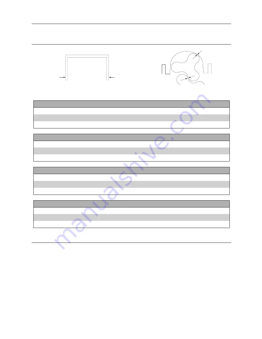
Alfa Laval SRU series Instruction Manual Download Page 43

6 Technical data

Radial Clearance

Front Clearance

Rotor Length

Back Clearance

Mesh Clearance

Minimum mesh clearance at any mesh position. All dimensions in millimeters

SRU6/260/LS (HS) TRILOBE and BILOBE ST.STL. ROTORS

10 BAR

Temperature

Rotor

Front

Back

Rotor

Radial

Min. MESH*

o

C

Length

Clearance

Clearance

Diameter

Clearance

TRILOBE

BILOBE 70

o

C

84.34

(min.)

0.25

201.27

(min.)

70

o

C

84.31

0.24

0.20

201.22

0.40

0.30

0.39

84.19

(min.)

0.25

201.13

(min.)

130

o

C

84.16

0.39

0.20

201.08

0.47

0.30

0.39

84.01

(min.)

0.25

200.97

(min.)

200

o

C

83.98

0.57

0.20

200.92

0.55

0.30

0.39

SRU6/260/LD (HD) TRILOBE and BILOBE ST.STL. ROTORS

20 BAR

Temperature

Rotor

Front

Back

Rotor

Radial

Min. MESH*

o

C

Length

Clearance

Clearance

Diameter

Clearance

TRILOBE

BILOBE 70

o

C

84.08

(min.)

0.35

200.67

(min.)

70

o

C

84.05

0.40

0.30

200.62

0.70

0.35

0.80

84.03

(min.)

0.35

200.53

(min.)

130

o

C

84.00

0.45

0.30

200.48

0.77

0.35

0.80

83.97

(min.)

0.35

200.37

(min.)

200

o

C

83.94

0.51

0.30

200.32

0.85

0.35

0.80

SRU6/353/LS (HS) TRILOBE and BILOBE ST.STL. ROTORS

7 BAR

Temperature

Rotor

Front

Back

Rotor

Radial

Min. MESH*

o

C

Length

Clearance

Clearance

Diameter

Clearance

TRILOBE

BILOBE 70

o

C

113.68

(min.)

0.25

201.11

(min.)

70

o

C

113.65

0.40

0.20

201.06

0.48

0.35

0.40

113.50

(min.)

0.25

200.91

(min.)

130

o

C

113.47

0.58

0.20

200.86

0.58

0.35

0.40

113.30

(min.)

0.25

200.67

(min.)

200

o

C

113.27

0.78

0.20

200.62

0.70

0.35

0.40

SRU6/353/LD (HD) TRILOBE and BILOBE ST.STL. ROTORS

15 BAR

Temperature

Rotor

Front

Back

Rotor

Radial

Min. MESH*

o

C

Length

Clearance

Clearance

Diameter

Clearance

TRILOBE

BILOBE 70

o

C

113.23

(min.)

0.45

200.47

(min.)

70

o

C

113.20

0.65

0.40

200.42

0.80

0.40

0.55

113.17

(min.)

0.45

200.27

(min.)

130

o

C

113.14

0.71

0.40

200.22

0.90

0.40

0.55

113.11

(min.)

0.45

200.03

(min.)

200

o

C

113.08

0.77

0.40

199.98

1.02

0.40

0.55

43

Summary of Contents for SRU series

Page 1: ...ESE00693 EN14 2017 09 Original manual Instruction Manual Rotary Lobe Pumps SRU Range ...

Page 2: ......

Page 3: ...nstallation 9 4 3 Flushing seal arrangement and pre start up checks 13 4 4 Recycling information 14 5 Maintenance 15 5 1 Cleaning in place CIP 15 5 2 Maintenance schedule 16 5 3 Dismantling 17 5 4 Assembly 20 5 5 Primary seals removal and fitting 27 5 6 Pressure relief valve 33 5 7 Heating Cooling devices 35 5 8 Troubleshooting 36 6 Technical data 37 6 1 Technical data 37 6 2 Pumphead Clearance in...

Page 4: ... hereby declare that Pump Designation SRU1 SRU2 SRU3 SRU4 SRU5 SRU6 Type From serial number 10 000 to 1 000 000 is in conformity with the following directive with amendments Machinery Directive 2006 42 EC The person authorised to compile the technical file is the signer of this document Global Product Quality Manager Pump Valves Fittings and Tank Equipment Lars Kruse Andersen Title Name Kolding 20...

Page 5: ...rawing shows only mounted unit Drive unit Gearbox Product seal area Ports Rotorcase Coupling guard encloses coupling Rotorcase cover TD 243 003_1 Baseplate fixing holes Pump duty conditions The pump should only be used for the duty for which it has been specified The operating pressure speed and temperature limits have been selected at the time of order and MUST NOT be exceeded These details are s...

Page 6: ...before using the pump WARNING Indicates that special procedures must be followed to avoid serious personal injury CAUTION Indicates that special procedures must be followed to avoid damage to the pump NOTE Indicates important information to simplify or clarify procedures 3 2 Warning signs General warning Dangerous electrical voltage Caustic agents Not applicable for Atex applications 6 ...

Page 7: ...ers inside the port connections or anywhere close to rotating parts Never run the pump unless fully assembled i e pump head must not be removed from gearcase Only handle toxic and acidic liquids in accordance with the manufacturers instructions and recommendations Maintenance Always read the technical data thoroughly See chapter 6 Technical data Never service the pump when it is hot The pump and t...

Page 8: ...away from the pump Inspect the pump for any visible signs of damage Clean away the packing from the pump port connections Report any damage immediately to the carrier Step 3 After receipt and inspection if the pump is not to be installed immediately the pump should be repacked and placed in suitable storage The following points should be noted Plastic or gasket type port covers should be left in p...

Page 9: ...nostic purposes Fit valves if two pumps are to be used on manifold common discharge lines Make the necessary piping arrangements if flushing is required for the seal or if a media is required for heating cooling jackets and saddles Allow at least 1 m for pump access maintenance all around the pump Do not subject rotary lobe pumps to rapid temperature changes as pump seizure can result from thermal...

Page 10: ...RU1 lbf 18 13 16 27 lbft 55 66 85 122 N 125 100 110 195 Nm 90 105 130 190 SRU2 lbf 28 22 25 44 lbft 66 77 96 140 N 165 135 150 260 Nm 100 115 140 205 SRU3 4 lbf 37 30 34 58 lbft 74 85 103 151 N 300 250 250 460 Nm 125 145 175 260 SRU5 6 lbf 67 56 56 103 lbft 92 107 129 192 Direction of flow The direction of flow is dictated by the direction of rotation of the drive shaft Reversing the direction of ...

Page 11: ...la S2 G150 Shell Omala S4 WE150 Texaco Meropa 150 Texaco Synlube CLP220 Esso Spartan EP150 Mobil Glygoyle 22 For ATEX applications refer to ATEX addendum manual Baseplate Foundations Pumps when supplied with a drive unit are normally mounted on a baseplate Our standard baseplates have pre drilled fixing holes to accept base retaining bolts To provide a permanent rigid support for securing the pump...

Page 12: ...ated tolerances can be corrected by applying shims under the motor or pump foot or by moving the pump or drive sideways on the baseplate All bolts that have been loosened should be re tightened to the stated torque figure The following dimensions and tolerances apply to standard supply couplings only Parallel misalignment Measure 4 positions at 90 around coupling Coupling size Dimension A Maximum ...

Page 13: ...uid being pumped and duty conditions i e pressure and temperature Usually water is used for cooling or flushing water soluble products For both single and flushed mechanical seal arrangements the temperature of flush media should never allowed to exceed the maximum temperature of the pumped media For advice on selecting a suitable flushing fluid please contact pump supplier Step 5 Flushing pressur...

Page 14: ...r parts in the machine are replaced All metal parts should be sent for material recycling Worn out or defective electronic parts should be sent to a licensed handler for material recycling Oil and all non metal wear parts must be taken care of in agreement with local regulations Scrapping At end of use the equipment shall be recycled according to relevant local regulations Beside the equipment its...

Page 15: ... 176 F at 2 5 dilution through the system for 20 30 minutes 3 Final flush through with cold water again Warnings Never touch the pump or the pipelines as they will be extremely hot Do not subject the pump to rapid temperature changes during CIP procedures as pump seizure can result from thermal shock A suitable by pass is recommended Always rinse well with clean water after using a cleaning agent ...

Page 16: ...l for any discoloration nicks or cracks If any of the defects above are noticed the O ring seal must be replaced Inspection and replacement refer to the seal replacement procedure below Seal Replacement Procedure 1 Remove rotor case cover see 5 3 Dismantling step Step 1 2 Undo rotor nuts and ensure components are dry before servicing 3 With a penlight inspect rotor nut blind tapped hole for contam...

Page 17: ...moved Plastic or wooden block Step 3 1 For packed gland seals loosen the gland followers to relieve the packing pressure on the shaft For flushed mechanical seal arrangements remove the seal housing retaining nuts and ease the seal housings from the rotorcase 2 Remove rotorcase retaining nuts 4 and washers 4A 3 Tap both sides of the rotorcase 9 with a soft mallet 4 Take care not to damage mechanic...

Page 18: ...reassembly Step 7 Removing timing gears 1 Release clamp plate screws 40 and remove clamp plate 39 on pump series 1 2 and 3 For pump series 4 5 and 6 remove the torque locking assembly screws in several stages 2 Remove gears 36 using the tapped extraction holes provided or remove shaft assembly as shown in step 8 below Step 8 Shaft assembly removal 1 Using a soft mallet gently tap the rear end of e...

Page 19: ...h thread locking adhesive 3 Mount the shaft vertically in a press with a tool positively located against the bearing inner as shown and apply pressure to the top of the shaft so that the shaft moves through the bearings 26 and 31 4 Remove each bearing set inner and outer Good engineering practice suggests that if bearings are removed from the shafts for any reason they should be renewed Clean and ...

Page 20: ...oft jaws and apply anti seize compound to the bearing diameters Step 2 Place the inner cone on the shaft ensuring a positive fit against the shaft shoulder Step 3 Locate outer cup bearing spacer 32 and rear bearing cup Step 4 Allow bearings to cool series 4 5 and 6 pumps only Failure to do so will result in incorrectly set bearings 1 Apply Permabond Grade 145 or equivalent locking compound to the ...

Page 21: ...abutment spacer will probably be needed It is vital to ensure the rotor alignments is within the limits set in section 5 4 4 5 4 3 Fitting seal retainers Step 1 Clean the rear face of the seal retainers 14 fit in position and tighten Step 2 1 Check rotor alignment is correct by reffering to the rotor abutment alignment in section 5 4 4 2 When rotor alignment is correct remove seal retainers and pr...

Page 22: ...de timing gears 36 onto shafts 24 and 25 realigning timing marks Step 2 1 Before fitting the torque locking devices 38 lubricate them with gear oil Series 1 2 and 3 high pressure pumps i e LD and HD models have two sets of elements 2 Series 4 5 and 6 pumps have torque locking assemblies Step 3 Fit timing gear clamp plates 39 series 1 2 and 3 only Fit torque locking assemblies 37 series 4 5 and 6 o...

Page 23: ...own with the rotor dimples in the 6 12 o clock plane horizontally ported pumps or 3 9 o clock plane vertically ported pumps For the rotor on the drive shaft the rotor dimple should be aligned with the drive shaft keyway Dimples Step 3 Turn the shaft so that the rotors are in the new positions as shown Step 4 Using feeler gauges measure between the points indicated turning the shaft as required Ste...

Page 24: ...pump serial number Should they need adjustment follow steps below Any incorrect setting of clearances is likely to damage the pump in operation Plastic shims vary in colour for different thickness and are grouped in packs at the top and bottom of the rotorcase held in place by shim retainers For temperatures greater than 130 C 266 F and or for ATEX stainless steel shims are fitted Shims can be sta...

Page 25: ...mmended torque figure Tighten the TLA screws to the recommended torque figure Unscrew the clamp plate tool and remove Replace the rotor cap and tighten to the recommended torque figure For Bi lobe rotors Fit rotors 17 onto the shafts 24 and 25 at an angle of 45 as shown Rotate pump one full revolution ensuring there is no rotor contact Step 2 Fit new O rings 20 to rotor retention nuts 22 Use a woo...

Page 26: ...ting rotorcase cover Step 1 1 Lightly smear new O ring 11 in grease and fit to rotorcase cover 12 2 Fit rotorcase cover onto rotorcase 9 and tighten rotorcase cover nuts 13 3 Refer to pump start up checks prior to operation 26 ...

Page 27: ...he grub screws 78 4 Remove the rotary seal assembly 74 from the shaft 5 Remove abutment spacer if fitted 6 Extract the rotary seal O ring 73 from the rotary seal assembly Seal fitting 1 Mark the shaft to indicate the seal setting length shown in table above 2 Lightly lubricate O rings 71 with appropriate grease and fit to stationary seals 72 3 Press the stationary seal rings into the rotorcase sea...

Page 28: ...Seal fitting 1 Lightly lubricate O rings 71 with appropriate grease and fit to stationary seal rings 72 2 Press the stationary seal rings into the rotorcase seal bores by aligning cut outs with the anti rotation pins 3 Wipe clean the stationary seal faces with solvent 4 Lightly lubricate lip seal 76 and seal housing bore with appropriate grease 5 Press lip seals into seal housings 79 6 Lightly lub...

Page 29: ...orcase 6 Remove seal housings 79 complete with rotary seal assemblies 74A and 74B and outboard stationary seals 7 Extract the seal housing O ring 75 stationary seal ring 72 and o ring 71 from the rotorcase Seal fitting Ensure seal orientation is correct Outboard Inboard Series 1 the outboard seal fits over the inboard seal Inboard Outboard Series 2 6 the inboard seal fits over the outboard seal 1 ...

Page 30: ... O rings 84 from the shafts Seal fitting 1 Lightly lubricate shaft O rings 84 with appropriate grease and fit to shafts 2 Lightly lubricate both sides of rubber washer 86 and fit to rotary seal rings 85 ensuring location under the drive pin 3 Slide the rotary seal rings on to the shafts lining up pins to slots on the shafts 4 Lightly lubricate rotorcase O rings 81 with appropriate grease and fit t...

Page 31: ... from the shafts Seal fitting 1 Lightly lubricate shaft O rings 84 with appropriate grease and fit to shafts 2 Lightly lubricate both sides of rubber washer 86 and fit to rotary seal rings 85 ensuring location under the drive pin 3 Slide the rotary seal rings on to the shafts lining up pins to slots on the shafts 4 Lightly lubricate rotorcase O rings 81 with appropriate grease and fit to rotorcase...

Page 32: ...e the O rings 1 fit to shaft sleeves 2 and locate on shafts 2 Tighten screws 10 and fit slingers 9 3 Fit gland spacer 3 gasket 6 and gland housing 7 to rotorcase 4 Insert the packing rings 4 and lantern ring 5 if fitted as shown ensuring joints are correctly spaced 5 Loosely locate the gland follower 8 and nuts 6 Refit rotorcase with packed assemblies over shaft sleeves 7 Adjust the packed gland P...

Page 33: ...elief valve Item Description Item Description 1 Rotorcase cover 14 Circlip 2 Hydraulic piston 15 Bush 3 O ring hydraulic piston 16 Valve guide 4 Valve pin 17 Valve pin 5 Shim 18 Spring 6 Backstop disc 19 Screw 7 O ring backstop disc 20 Valve spring guide 8 Bush 21 Spring adjuster 9 Screw backstop disc 22 Washer 10 Valve shaft 23 Notched nut 11 O ring pneumatic piston 24 Valve housing 12 Pneumatic ...

Page 34: ...circlip 14 and springs 18 Series 6 pumps only each spring stack should contain an equal amount of springs noting correct orientation Place valve guide 16 over springs and replace screws 26 6 Fit spring adjuster 21 and notched nut 23 valve housing 24 and screw 25 7 Replace manual override lever if applicable 5 6 3 Valve Adjustment The relief valve will require setting to suit duty requirements Note...

Page 35: ...jackets and saddles should be in operation approximately 15 minutes prior to pump start up and remain in operation 15 minutes after pump shut down Assembly 1 Clean faces where sealant is to be applied 2 Apply Loctite 5970 silicone sealant or equivalent to face of heating jacket saddle allow to dry for approx 5 10 minutes 3 Locate cap screws in jacket saddle and align screws with tapped holes in ro...

Page 36: ...ge pressure above rated figure Simplify discharge line to decrease pressure Gland over tightened Slacken and re adjust gland packing Gland under tightened Adjust gland packing Increase flush flow rate Seal flushing inadequate Check that flush fluid flows freely into seal area Pump speed above rated figure Decrease pump speed Pump speed below rated figure Increase pump speed Check alignment of pipe...

Page 37: ...rizontal Vertical Horizontal Vertical SRU1 005 15 33 16 35 45 99 46 101 SRU1 008 17 37 18 40 55 121 56 123 SRU2 013 28 62 30 66 75 165 77 170 SRU2 018 29 64 31 68 80 176 82 181 SRU3 027 53 117 56 123 145 320 148 326 SRU3 038 56 123 59 130 150 331 153 337 SRU4 055 105 231 111 245 260 573 266 586 SRU4 079 110 243 116 256 265 584 271 597 SRU5 116 148 326 185 408 396 873 433 955 SRU5 168 156 344 193 4...

Page 38: ... 10 10 10 25 25 25 Seal retainer screw 15 Torque Setting lbft 7 4 7 4 7 4 18 4 18 4 18 4 Key Size mm 5 5 5 6 6 6 Torque Setting Nm 10 10 10 25 25 25 Gearcase cover screw 6 Torque Setting lbft 7 4 7 4 7 4 18 4 18 4 18 4 Key Size mm 5 5 5 5 6 6 Torque Setting Nm 12 17 12 14 35 35 TLA Clamp plate screw 40 Torque Setting lbft 8 9 12 5 8 9 10 3 25 8 25 8 Drain plug 45 Key Size in Key Size mm 5 6 6 8 10...

Page 39: ...9 LD or HD 0 790 17 38 20 87 65 2 5 80 3 0 15 215 1000 47 40 SRU5 116 LS or HS 1 160 25 52 30 64 65 2 5 80 3 0 10 145 600 41 76 SRU5 116 LD or HD 1 160 25 52 30 64 65 2 5 80 3 0 20 290 600 41 76 SRU5 168 LS or HS 1 680 36 95 44 38 80 3 0 100 4 0 7 100 600 60 48 SRU5 168 LD or HD 1 680 36 95 44 38 80 3 0 100 4 0 15 215 600 60 48 SRU6 260 LS or HS 2 600 57 19 68 68 100 4 0 100 4 0 10 145 500 78 00 S...

Page 40: ...63 min 0 12 86 28 min 70oC 22 60 0 14 0 07 86 24 0 16 0 08 0 24 22 52 min 0 15 86 22 min 130oC 22 49 0 22 0 10 86 18 0 19 0 08 0 24 22 35 min 0 22 86 18 min 200oC 22 32 0 32 0 17 86 14 0 21 0 08 0 24 SRU2 013 LD HD TRILOBE and BILOBE ST STL ROTORS 15 BAR Temperature Rotor Front Back Rotor Radial Min MESH oC Length Clearance Clearance Diameter Clearance TRILOBE BILOBE 70oC 22 48 min 0 18 86 20 min ...

Page 41: ...70oC 43 11 0 17 0 10 107 71 0 26 0 13 0 40 43 00 min 0 18 107 64 min 130oC 42 97 0 28 0 13 107 59 0 32 0 13 0 40 42 79 min 0 25 107 52 min 200oC 42 76 0 42 0 20 107 47 0 38 0 13 0 40 SRU3 038 LD HD TRILOBE and BILOBE ST STL ROTORS 10 BAR Temperature Rotor Front Back Rotor Radial Min MESH oC Length Clearance Clearance Diameter Clearance TRILOBE BILOBE 70oC 42 99 min 0 26 107 48 min 70oC 42 96 0 25 ...

Page 42: ...70oC 51 04 0 25 0 13 172 53 0 28 0 20 0 31 50 99 min 0 18 172 46 min 130oC 50 96 0 33 0 13 172 41 0 34 0 20 0 31 50 94 min 0 18 172 32 min 200oC 50 91 0 38 0 13 172 27 0 41 0 20 0 31 SRU5 116 LD HD TRILOBE and BILOBE ST STL ROTORS 20 BAR Temperature Rotor Front Back Rotor Radial Min MESH oC Length Clearance Clearance Diameter Clearance TRILOBE BILOBE 70oC 50 98 min 0 20 172 22 min 0 20 0 31 70oC 5...

Page 43: ...84 05 0 40 0 30 200 62 0 70 0 35 0 80 84 03 min 0 35 200 53 min 130oC 84 00 0 45 0 30 200 48 0 77 0 35 0 80 83 97 min 0 35 200 37 min 200oC 83 94 0 51 0 30 200 32 0 85 0 35 0 80 SRU6 353 LS HS TRILOBE and BILOBE ST STL ROTORS 7 BAR Temperature Rotor Front Back Rotor Radial Min MESH oC Length Clearance Clearance Diameter Clearance TRILOBE BILOBE 70oC 113 68 min 0 25 201 11 min 70oC 113 65 0 40 0 20...

Page 44: ...7 Parts list 7 1 SRU1 Pump Range 7 6 5 45 47 49 53 50 52 51 54 58 8 8A 3 8B 13 12 11 10 9 15 14 16 2 1 4A 4 48 46 58 56 36 38 39 40 26 27 30 23 31 32 18 25 24 22 20 17 TD 243 052 44 ...

Page 45: ...6 Screw seal retainer 16 2 Lip seal gland end 17 2 Rotor 18 2 O Ring rotor sealing shaft end 20 2 O Ring rotor sealing nut end 22 2 Nut rotor retention 23 1 Key 24 1 Shaft drive 25 1 Shaft auxiliary 26 2 Bearing rear 27 1 Spacer shaft abutment 30 2 Nut bearing 31 2 Bearing front 32 2 Spacer bearing 36 2 Timing gear 38 2 Torque locking element 39 2 Clamp plate 40 12 Screw clamp plate 45 2 Drain plu...

Page 46: ...7 Parts list 7 2 SRU2 Pump Range 7 6 5 45 47 49 53 50 52 51 54 58 8 8A 3 8B 13 12 11 10 9 15 14 16 2 1 4A 4 48 46 58 56 36 38 39 40 26 27 30 23 31 32 18 25 24 22 20 17 TD 243 052 46 ...

Page 47: ...crew seal retainer 16 2 Lip seal gland end 17 2 Rotor 18 2 O Ring rotor sealing shaft end 20 2 O Ring rotor sealing nut end 22 2 Nut rotor retention 23 1 Key 24 1 Shaft drive 25 1 Shaft auxiliary 26 2 Bearing rear 27 1 Spacer shaft abutment 30 2 Nut bearing 31 2 Bearing front 32 2 Spacer bearing 36 2 Timing gear 38 2 Torque locking element 39 2 Clamp plate 40 12 Screw clamp plate 45 2 Drain plug 4...

Page 48: ...7 Parts list 7 3 SRU3 Pump Range 7 6 5 45 47 49 53 50 52 51 54 58 8 8A 3 8B 13 12 11 10 9 15 14 16 2 1 4A 4 48 46 58 56 36 38 39 40 26 27 30 23 31 32 18 25 24 22 20 17 TD 243 052 48 ...

Page 49: ...6 Screw seal retainer 16 2 Lip seal gland end 17 2 Rotor 18 2 O Ring rotor sealing shaft end 20 2 O Ring rotor sealing nut end 22 2 Nut rotor retention 23 1 Key 24 1 Shaft drive 25 1 Shaft auxiliary 26 2 Bearing rear 27 1 Spacer shaft abutment 30 2 Nut bearing 31 2 Bearing front 32 2 Spacer bearing 36 2 Timing gear 38 2 Torque locking element 39 2 Clamp plate 40 12 Screw clamp plate 45 2 Drain plu...

Page 50: ...7 Parts list 7 4 SRU4 Pump Range 7 6 5 45 47 49 53 50 52 51 54 58 8 8a 3 8b 13 12 11 10 9 15 14 16 2 1 4a 4 48 46 58 56 36 37 30 26 27 26 28 23 31 34 18 25 24 22 20 17 TD 243 053 31 29 50 ...

Page 51: ...tainer 16 2 Lip seal gland end 17 2 Rotor 18 2 O Ring rotor sealilng shaft end 20 2 O Ring rotor sealing nut end 22 2 Nut rotor retention 23 1 Key 24 1 Shaft drive 25 1 Shaft auxiliary 26 4 Bearing rear 27 1 Spacer shaft abutment 28 2 Spacer bearing drive end 29 2 Spacer bearing gland end 30 2 Nut bearing rear 31 4 Bearing front 34 2 Nut bearing front 36 2 Timing gear 37 2 Torque locking assembly ...

Page 52: ...7 Parts list 7 5 SRU5 Pump Range 58 54 50 52 51 45 53 49 5 7 6 47 16 13 12 11 10 8 8a 8b 14 15 23 24 18 17 1 2 3 46 4a 4 45 56 37 58 22 20 36 25 31 29 31 34 27 26 28 26 30 3201 0011 9 52 ...

Page 53: ...6 Screw seal retainer 16 2 Lip seal gland end 17 2 Rotor 18 2 O Ring rotor sealing shaft end 20 2 O Ring rotor sealing nut end 22 2 Nut rotor retention 23 1 Key 24 1 Shaft drive 25 1 Shaft auxiliary 26 4 Bearing rear 27 1 Spacer shaft abutment 28 2 Spacer bearing drive end 29 2 Spacer bearing gland end 30 2 Nut bearing rear 31 4 Bearing front 34 2 Nut bearing front 36 2 Timing gear 37 2 Torque loc...

Page 54: ...7 Parts list 7 6 SRU6 Pump Range 58 54 50 52 51 45 53 49 5 7 6 47 16 13 12 11 10 8 8a 8b 14 15 23 24 18 17 1 2 3 46 4a 4 45 56 37 58 22 20 36 25 31 29 31 34 27 26 28 26 30 3201 0012 9 19 54 ...

Page 55: ...etainer 16 2 Lip seal gland end 17 2 Rotor 18 2 O Ring rotor sealing shaft end 19 2 Torque locking assembly 20 2 O Ring rotor sealing nut end 22 2 Nut rotor retention 23 1 Key 24 1 Shaft drive 25 1 Shaft auxiliary 26 4 Bearing rear 27 1 Spacer shaft abutment 28 2 Spacer bearing drive end 29 2 Spacer bearing gland end 30 2 Nut bearing rear 31 4 Bearing front 34 2 Nut bearing front 36 2 Timing gear ...

Page 56: ...is the responsibility of the user of this document to comply with all applicable intellectual property laws Without limiting any rights related to this document no part of this document may be copied reproduced or transmitted in any form or by any means electronic mechanical photocopying recording or otherwise or for any purpose without the expressed permission of Alfa Laval Corporate AB Alfa Lava...

Reviews: