15/21
ALFA IN a.s. ©
www.alfain.eu
ADJUSTING WELDING PARAMETERS FOR MIG MAN
1. Approximate setting for the MIG / MAG welding current and voltage
corresponds the empirical relationship U2 = 14 +0.05 I2. According to this
relationship, we can determine the required voltage. When setting the
voltage, we expect the decline in voltage during load. The voltage drop is
approximately 4.5-5.0 V at 100 A.
2. By means of the potentiometer
30
select voltage.
3. Then by means of the potentiometer
31
select the appropriate wire speed.
4. By means of the potentiometer
29
tune the arc by changing the levels of
the choke.
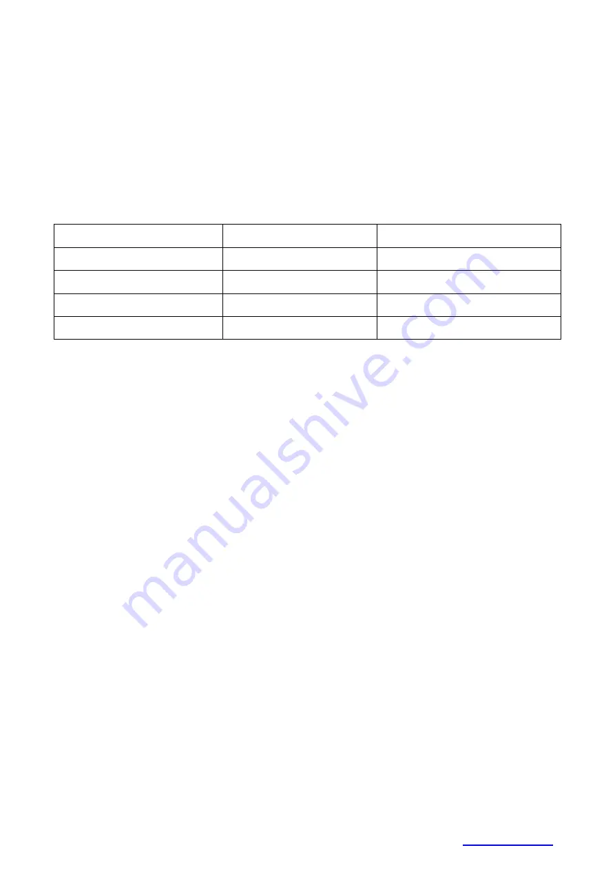
Wire diameter (mm)
Welding current (A)
Material thickness (mm)
0,6
25 - 110
1,0 - 1,6
0,8
35 - 160
1,0 - 2,3
0,9
45 - 160
1,0 - 2,3
1,0
45 - 200
1,2 - 7,0
Table of approximate parameter settings
ADJUSTING THE MACHINE FOR ANOTHER WIRE DIAMETER
In all machines ALFA IN MIG / MAG are used rolls with two grooves. These
grooves are intended for two different wire diameters (e.g. 0,8 a 1,0 mm). Groove
can be replaced by removing the rolls and rotating them, or use a different roll
grooves with required dimensions.
1. Open the nut
E1
to the right, pressure roll
E2
will be opened upward.
2. Unscrew the plastic locking element
E5
and remove the roll.
3. If there is a suitable groove on the roll, rotate the roll and place it back on
the shaft and secure it by screwing the element
E5
.
FLUX CORE WIRE – SETTING THE POLARITY FOR MIG/MAG TORCH
1. It is desirable to have positive polarity on the MIG/MAG torch while welding
with solid wire in majority of cases. The welder is supplied from the production
with positive polarity on the MIG/MAG torch.
2. For welding with flux cored wires it may be necessary to have negative
polarity on the MIG/MAG torch.
3. The middle terminal
K3
is connected to the central euro connector of the
MIG/MAG torch. We supply the welder with
K3
connected to (+)
K1
.
4. In case of welding with flux core wire with (-) polarity, connect
K3
by means
the bridge
K2
with
K4
terminal. Use Phillips screwdriver.
5. Make sure you fasten the terminals properly.
6. Connect the ground cable to the
(+) panel socket, fig. 1, pos.
7
.


