background image

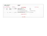
UB0MNC - Main PCB Rev C

Last Revised:

RevChange Document

10/26/2005

SCH PCB CAM

Suggested 

by:

DATE

Performed 

by:

DATE

Description of change:

Reason for change:

TOP LEVEL CHANGES

x

x

SOP

10/12/2005

JK

10/26/2005

Change all text from Rev B to C

SOP

x

x

SOP

10/12/2005

JK

10/26/2005

update all Part Types

SOP

SOP

10/12/2005

Review/Integrate all outstanding ECNs

SOP

Note: ***A new solderpaste stencil IS required***

A component was removed.

x

x

YHT

10/12/2005

JK

10/26/2005

Ground the USB shield directly to GND instead of through 
ferrite bead. Remove ferrite bead L2.

EMC compliance.

SCHEMATIC CHANGES

PCB CHANGES

Summary of Contents for IO|2

Page 1: ... and confidential information It is intended only for the use of those authorized by Alesis If you are not the authorized intended recipient you are hereby notified that any review dissemination distribution or duplication of this document is strictly prohibited If you are not authorized please contact Alesis and destroy all copies of this document You may contact Alesis at servicemanuals alesis c...

Page 2: ...ity and Alesis shall have no liability for any such repairs or service work All such service or repairs are performed at the sole risk of the person performing the service or repairs You agree that all such work will be performed in a competent professional and safe manner at all times and to indemnify and fully hold Alesis and its successors and assigns harmless in the event of any failure to so ...

Page 3: ...ZED REPAIR SERVICE CENTER IN THE PROVISION OF REPAIR SERVICES OR TO BE OR MAKE REPAIRS AS AN AUTHORIZED SERVICE CENTER ALL REPAIRS DONE BY ANY ENTITY OTHER THAN AN AUTHORIZED ALESIS SERVICE CENTER SHALL BE SOLELY THE RESPONSIBILITY OF THAT ENTITY AND ALESIS SHALL HAVE NO LIABILITY TO THAT ENTITY OR TO ANY OTHER PARTY FOR ANY REPAIRS BY THAT ENTITY Regarding the Power Supply Fuse CAUTION The produc...

Page 4: ... producing equipment 7 Ventilation When installing the product make sure that the product has adequate ventilation Improperly ventilating the product may cause overheating which may damage the product 8 Mounting The product should only be used with a rack which the manufacturer recommends The combination of the product and rack should be moved carefully Quick movements excessive force or uneven su...

Page 5: ...ALESIS IO 2 UB0 SCHEMATIC AND PCB FILES Confidential Alesis Service Manual 8 31 0137 A ...

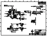
Page 6: ...MAIN PCB REV F Confidential Alesis Service Manual 8 31 0137 A ...
Page 7: ......

Page 8: ......

Page 9: ......

Page 10: ......

Page 11: ......

Page 12: ......

Page 13: ......

Page 14: ......

Page 15: ......

Page 16: ......

Page 17: ......

Page 18: ......

Page 19: ......

Page 20: ......

Page 21: ......

Page 22: ......

Page 23: ... negative terminal and C76 s positive terminal are too close x YH 3 16 2006 JK 3 16 2006 The bottom layer pads of C43 s negative terminal and C44 s positive terminal are too close x YH 3 16 2006 JK 3 16 2006 The bottom layer pads of C57 s negative terminal and C68 s positive terminal are too close x YH 3 16 2006 JK 3 16 2006 The bottom layer pad of C40 s negative terminal is too close to C41 s 3 3...

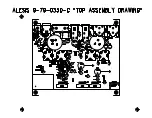
Page 24: ...MAIN PCB REV E Confidential Alesis Service Manual 8 31 0137 A ...
Page 25: ......

Page 26: ......

Page 27: ......

Page 28: ......

Page 29: ......

Page 30: ......

Page 31: ......

Page 32: ......

Page 33: ......

Page 34: ......

Page 35: ......

Page 36: ......

Page 37: ......

Page 38: ......

Page 39: ......

Page 40: ......

Page 41: ...Rev D to E SOP x x SOP 12 2 2005 JK 3 13 2006 update all Part Types SOP SOP 12 2 2005 Review Integrate all outstanding ECNs SOP Note A new solderpaste stencil IS NOT required No components were changed or moved x x JK 3 10 2006 JK 3 13 2006 Correct implementation of input protection diodes and 100 Ohm series resistors The current implementation does not provide much protection if any at all SCHEMA...

Page 42: ...MAIN PCB REV D Confidential Alesis Service Manual 8 31 0137 A ...

Page 43: ......

Page 44: ......

Page 45: ......

Page 46: ......

Page 47: ......

Page 48: ......

Page 49: ......

Page 50: ......

Page 51: ......

Page 52: ......

Page 53: ......

Page 54: ......

Page 55: ......

Page 56: ......

Page 57: ......

Page 58: ......

Page 59: ...100ohm resistors between input DC blocking caps C25 30 31 35 and protection diodes D3 10 Protect negative voltage regulator from damage due to short This was implemented as rework pre production so there is no ECN x AWS 11 28 2005 AWS 11 28 2005 Resize holes on MIDI jack footprint 49 2mil for shield pin 43 3 mil for other pins Yahourng request x AWS 11 28 2005 AWS 11 28 2005 Resize holes on XLR ja...

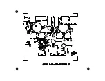
Page 60: ...MAIN PCB REV C Confidential Alesis Service Manual 8 31 0137 A ...
Page 61: ......

Page 62: ......

Page 63: ......

Page 64: ......

Page 65: ......

Page 66: ......

Page 67: ......

Page 68: ......

Page 69: ......

Page 70: ......

Page 71: ......

Page 72: ......

Page 73: ......

Page 74: ......

Page 75: ......

Page 76: ......

Page 77: ...26 2005 Change all text from Rev B to C SOP x x SOP 10 12 2005 JK 10 26 2005 update all Part Types SOP SOP 10 12 2005 Review Integrate all outstanding ECNs SOP Note A new solderpaste stencil IS required A component was removed x x YHT 10 12 2005 JK 10 26 2005 Ground the USB shield directly to GND instead of through ferrite bead Remove ferrite bead L2 EMC compliance SCHEMATIC CHANGES PCB CHANGES ...

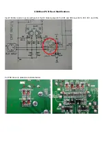
Page 78: ...UB0 Main PCB Rev C Modifications Insert 100ohm resistor in series with each of the DC blocking caps for the CH1 and CH2 input C25 C30 C31 and C35 Cut PCB traces 4 places as indicated below ...

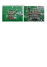
Page 79: ...Solder a 100ohm resistor onto PCB to bridge the cut 4 places ...

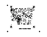
Page 80: ...FRONT PANEL PCB REV C Confidential Alesis Service Manual 8 31 0137 A ...
Page 81: ......

Page 82: ......

Page 83: ......

Page 84: ......

Page 85: ......

Page 86: ......

Page 87: ......

Page 88: ......

Page 89: ......

Page 90: ...ew Integrate all outstanding ECNs SOP x AWS 11 20 2005 AWS 11 28 2005 Resize drill hole in ribbon cables footprints Yahourng Request x AWS 11 28 2005 AWS 11 28 2005 Modify footprint of 1 08 0222 for 1mm hole size Yahourng request x x MBL 9 26 2005 AWS 11 20 2005 Change headphone volume control from post Main volume to pre so that the Main and Headphone volumes are independent Multiple user request...

Page 91: ...FRONT PANEL PCB REV B Confidential Alesis Service Manual 8 31 0137 A ...
Page 92: ......

Page 93: ......

Page 94: ......

Page 95: ......

Page 96: ......

Page 97: ......

Page 98: ......

Page 99: ......

Page 100: ......

Page 101: ... 2005 JK 9 21 2005 Change revision to Rev B SOP SOP 9 20 2005 Update all Part Types SOP SOP 9 20 2005 Review Integrate all outstanding ECNs SOP Note A new solderpaste stencil IS NOT required No components are changed SCHEMATIC CHANGES PCB CHANGES JK 9 20 2005 JK 9 21 2005 Increase hole size for LEDs Current hole size is just a little tight which would make manufacturing more difficult ...

Page 102: ...ALESIS IO 2 UB0 ECN HISTORY Confidential Alesis Service Manual 8 31 0137 A ...
Page 103: ......

Page 104: ...ENGINEERING CHANGE NOTICE LGO7401 3 15 06 PRODUCT S UBO ASSEMBL Y S 9 79 0350 0 ECN DATE WAS PCBMAIN UBO REV D 9 40 0350 D IS PCBMAIN UBO REV E 9 40 0350 E REASON FOR CHANGE i PRo r GiNEiR DlREcr ...

Page 105: ...ALESIS IO 2 UB0 BOM Confidential Alesis Service Manual 8 31 0137 A ...
Page 106: ...NT PANEL UB0 1 9 79 0350 ASSY PCB MAIN UB0 0 15 0101 RES 100 OHM 1 10W 5 0805 8 R1 2 R4 R24 R66 R93 R104 R115 0 15 0109 RES 1 0 OHM 1 10W 5 0805 10 R12 15 R42 45 R97 R119 0 15 0152 RES 1 5K OHM 1 10W 5 0805 1 R17 0 15 0153 RES 15K OHM 1 10W 5 0805 8 R34 37 R51 52 R54 55 0 15 0221 RES 220 OHM 1 10W 5 0805 2 R9 R101 0 15 0331 RES 330 OHM 1 10W 5 0805 3 R11 R61 R71 0 15 0473 RES 47K OHM 1 10W 5 0805 ...
Page 107: ... SIGNAL PNP 65V 100mA BC856 SOT 23 4 Q6 9 2 54 2114 TRANS SMALL SIGNAL NPN 2SD2114K SOT 23 6 Q1 Q4 Q10 Q13 14 Q17 2 54 6306 TRANS SMALL SIGNAL DUAL P CHAN EN MOSFET FDC6306P ISOLATE 2 U6 7 2 61 2985 IC REG VOLTAGE LP2985IM5 4 0 LDO 4V 150mA SOT23 5 1 U8 2 61 3578 IC REG VOLTAGE IC REG VOLTAGE LM3578A ADJ 100KHz PWM SWITC 1 U10 2 61 7223 REG VOLTAGE NJU7223DL1 33 3 3V TO 252 2 U1 U3 2 62 0157 IC 74...

Page 108: ... C12 16 C19 20 C22 24 1 55 0471 CAP 470pF 5 NPO 0805 50V 2 C8 9 1 56 0101 CAP 100pF NPO 0805 5 50V 2 C2 C5 1 56 0104 CAP 0 1uF X7R 0805 10 50V 4 C4 C10 11 C18 1 56 0150 CAP 15pF NPO 0805 2 C17 C21 2 50 4148 DIODE SIGNAL LS4148 MELF 3 D7 D10 11 2 71 3079 IC MC33079 QUAD OP AMP SOP 14 1 U4 2 71 7082 IC NJU7082BM DUAL POWER OP AMP LOW VOLTAGE SOP 8 0 2 1 U1 2 72 0339 IC LM339 ANALOG COMP SOP 14 2 U2 ...

Reviews: