ALENCON AID 1000 Installation, Operation And Maintenance Manual Download Page 1


Alencon Systems 

 Passionate About Power 

COPYRIGHT © 2020 ALENCON LLC, INC. | ALL RIGHTS RESERVED. 
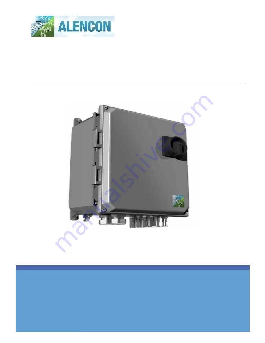
AID 

 Alencon Isolated 

Disconnect


A PV disconnect solution for DC-DC Optimizers and Solar + Storage 
Devices


Installation, Operation and Maintenance Manual for use with all 
variants of the AID product. 

Summary of Contents for AID 1000

Page 1: ...YRIGHT 2020 ALENCON LLC INC ALL RIGHTS RESERVED AID Alencon Isolated Disconnect A PV disconnect solution for DC DC Optimizers and Solar Storage Devices Installation Operation and Maintenance Manual fo...

Page 2: ...NFGI 02 ____ 3 21 2022 J Faber HF Add open and close instructions Disclaimer Alencon LLC makes no representations express or implied with respect to this documentation or any of the equipment and or s...

Page 3: ...rounding Ground Fault Indication 10 5 Installation 11 5 1 Mounting Procedure Separate Mounting Bracket 11 5 2 Mounting Procedure SPOT BOSS Side Mounted 12 5 3 Connecting to Input and Output 14 6 Servi...

Page 4: ...ID UNIT 6 FIGURE 2 AID CONFIGURATION MATRIX 6 FIGURE 3 ALENCON ISOLATED DISCONNECT INTERNAL VIEW 9 FIGURE 4 DISCONNECT SWITCH LOCKABLE 9 FIGURE 5 AID ENCLOSURE 10 FIGURE 6 AID MOUNTING BRACKET INSTALL...

Page 5: ...its products will be free from defects in materials and workmanship for three years from the date of purchase Extended warranteesof an additionalfive 5 ten 10 and twenty 20 yearsare alsoavailable for...

Page 6: ...all Alencon Systems or your licensed Alencon Systems dealer and describe the problem Please have your manual product and any helpful information readily available If your product is diagnosed as defec...

Page 7: ...ensure the following items have been shipped Commensurate of AID units specified for your project 1 x Warranty Card 4 x 1 4 20 zinc plated slotted indented hex washer head thread cutting screws for S...

Page 8: ...Input Device 30A 120A 13A 52A Weather Rating IP65 Fusing Optional 10A 15A 20A 30A Dimensions H W D 360mm 290mm 190mm Weight 4 7 kg depending on configuration Certification Switch UL 508i Case UL 508A...

Page 9: ...ring operation hazardous voltages and currents may be present Only authorized and qualified personnel should perform servicing installation 3 Exposed PV strings to sunlight represent a shock hazard at...

Page 10: ...and or a fuse to ground that can easily be included as options Please consult your Alencon technical sales consultant for assistance in determining which AID configuration is right for your needs FIGU...

Page 11: ...c mounting brackets and a gasket system encased in a continuous channel on the cover assure long life and water tightness FIGURE 5 AID ENCLOSURE 4 5 Grounding Ground Fault Indication Ground fault indi...

Page 12: ...the OFF OPEN position before beginning the install process 5 1 Mounting Procedure Separate Mounting Bracket 1 AID is shipped already mounted on the Alencon Bracket see Figure 6 2 Lift the AID so that...

Page 13: ...are attached see Figure 8 2 Adjust the positioning of the legs to line them up with the grooves on the side of the SPOT BOSS chassis see Figure 9 3 The AID can be mounted on either side of the SPOT B...

Page 14: ...Alencon SPOT Installation Operation and Maintenance Manual 13 P a g e FIGURE 9 SPOT DEVICE MOUNTING GROOVES HIGHLIGHTED FIGURE 10 SPOT WITH SIDE MOUNTED AID...

Page 15: ...Connect PV Strings to appropriate PV IN Amphenol H4 connectors on the bottom of the AID see Figure 11 FIGURE 11 BOTTOM VIEW OF AID INPUT PORTS 2 Connect PV wires from the AID to the corresponding SPOT...

Page 16: ...t from the gray switch base using a 7 8 inch socket wrench 7 Remove the gray switch base from the silver switch head with yellow thread 8 Unscrew 4 lid corner screws using a Phillips 2 screwdriver 9 R...

Page 17: ...OFF the AID 2 Open the AID enclosure see section 6 1 1 3 Use a multimeter to check internal fuses for continuity 4 If any fuses are blown discontinuous open the fuse holder 5 Remove dead fuse and rep...

Page 18: ...messages may lead to severe or lethal injuries due to electric shock To avoid electric shock from live voltage Wear class 2 personal protective equipment Always perform work in compliance with the re...

Page 19: ...isible damage Regularly check the equipment for visible damage Make sure that all external safety equipment is always freely accessible Make sure that all safety equipment is in good working order A 3...

Page 20: ...he equipment Keep the electrical bus channel covered Appendix B Glossary Word s Acronyms Definition ALS ALENCON Systems LLC DC Direct Current ESD Electrostatic Discharge ESS Energy Storage System FEED...

Page 21: ...tems web site at www alenconsystems com where you can find the latest information about the product Contact your distributor sales representative or Alencon Systems technical support if you need addit...

Reviews: