background image

AIR PURGE AND TEST OPERATION

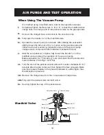
When Using The vacuum Pump


       (For method using a manifold valve, refer to this operation manual.)

Completely tighten the flare nuts, A, B, C, D, connect the manifold valve 

charge hose to a charge port of low-pressure valve on the gas pipe side. 

Connect the charged hose connection to the vacuum pump.

Fully open the handle “Lo” of the manifold valve.

Operate the vacuum pump to evacuate. After starting the evacuation, 

slightly loosen the flare nut of the “Lo” valve on the gas pipe side and 

check that the air is entering. (Operation noise of the vacuum pump 

changes and a compound meter indicated 0 instead of minus)

After the evacuation is complete, fully loosen the handle “Lo” of the  

manifold valve and stop the operation of the vacuum pump. 

Make evacuation for 15 minutes or more and check that the compound 

meter indicates -76cmHg(-1.0x10 Pa).

Turn the stem of the packed valve B about 45

o

 counter clockwise for 6~7 

seconds after the gas comes out, then tighten the flare nut again. Make 

sure the pressure display in the pressure indicator is a little higher than 

the atmosphere pressure.

Remove the charge hose from the  Low pressure charge hose.

Fully open the packed valve stems B and A.

Securely tighten the cap of the packed valve.

i.

ii. 


iii.

iv.

v.

vi.

vii.

viii.

ix. 

Manifold valve

Compound meter

Pressure gauge

Handle “HI” 

Handle “LO” 

Charge hose

Charge hose

Vacuum pump

Low pressure valve

-76cmHg

14

Summary of Contents for AMS09

Page 1: ... WARNING CAUTION This symbol refers to hazard or unsafe practices which can result in severe personal injury or death This symbol refers to hazards or unsafe practices which can result in severe personal injury or death and the potential for product or property damage Electrical Hazard Symbols ELECTRICAL SAFETY ALERT ...

Page 2: ...ctive Pipe and Drainage Installation 3 Indoor Unit Installation 4 Wiring 5 Connecting Cables Condensor Outdoor Unit Installtion 1 Outdoor Installation Precautions 2 Drain Elbow Installation 3 Refrigerant Piping Connection 4 Wiring Connection AIR PURGE TEST 1 Air Purge 2 Gas Leak Check 3 Test Operation 1 For warranty information please refer to www alencorp com ...

Page 3: ...danger warning and caution notices given in this manual Have it installed by a certified professional Always use a certified HVAC professional to install the split air conditioning system to prevent damage to the unit or injury to yourself The vacuuming and charging of the line set is required during installation Improper instal lation can result in water or refrigerant leakage electrical shock or...

Page 4: ...t all wiring tightly Loose wiring may cause overheating at connection points and a possible fire hazard When Installing In a Ceiling or Wall Make sure the ceiling wall is strong enough to hold the unit s weight It may be necessary to construct a strong wood or metal frame to provide added support In a Room Properly insulate any tubing run inside a room to prevent sweating that can cause dripping a...

Page 5: ...tallation explain correct operation to the customer using the operating manual This air conditioner uses R410A Please make note of these differences 1 Since the working pressure is 1 6 times higher than that of conventional refrigerant R22 models some of the piping and installation and service tools may be different 2 Models that use refrigerant R410A have a different charging port thread diameter...

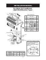
Page 6: ...e Controller 1 6 Seal 1 7 Drain Elbow 1 Parts Installation INSTALLATION MANUAL For Room Air Conditioner Split Wall Mounted Type MODEL A inches B inches 12000Btu h 215 105 12000Btu h 208 114 Anchor Bolts for Condensor Installation The condensor unit should not be exposed to strong wind Fix the condensor unit with O 3 8 anchor bolts AIR INLET AIR OUTLET BOLTS BOLTS BOLTS BOLTS A B 5 ...

Page 7: ... least 6 inches above and 5 inches on either side of the unit Condensor Unit Outdoor Unit If possible do not install the unit where it will be exposed to direct sunlight If necessary install a blind that does not interfere with the air flow Do not install the unit where a strong wind blows or where it is very dusty Do not install the unit where people can come into contact with the unit Install in...

Page 8: ...tape to the bottom of piping Prevent drain water from freezing in low temperature environments When installing evaporator indoor unit s drain hose outdoors necessary mea sures for frost protection should be taken to prevent the drain hose from freezing becoming blocked which could result in water leakage Measures for frost protection should be taken to prevent the drain hose from freezing becoming...

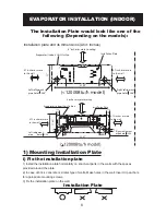
Page 9: ... the installation plate 1 Install the installation plate horizontally on structural parts in the walls with the spaces provided around the plate 2 In case of brick concrete or similar type of walls Make holes in the wall Insert clip anchors for appropriate mounting screws 3 Fix the installation plate on the wall Installation Plate Evaporator Indoor Unit Outline 6 inches or more to ceiling Installa...

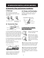
Page 10: ...he connective pipe Refer to Tightening Connection in Refrigerant Piping Connection Connective Pipe Evaporator Indoor Unit outline iii Piping and Bandaging Connective Cable Ponding Box Pipe Room Connective Pipe Wrapping Belt Drain Hose Wind the Connective cable drain hose and wiring tape securely evenly as shown below Evaporator Indoor Unit i Pass the piping through the hole in the wall ii Put the ...

Page 11: ...air conditioner Model Power Source Plug socket and fuse rating AWG MIN Power Supply Cord Connecting Cable 12000Btu h 60 Hz 115V 32 25A 14 18 12000Btu h 5 Connecting Cables i Evaporator Indoor and Condensor Outdoor connecting cable should be Aw18 or more ii Remove the panel and screw then remove the window cover for 12000Btu h models Remove the panel screws covers then remove the screws and take ou...

Page 12: ...cket and wall bracket and the air conditioner should be firm stable and reliable Be sure there is no obstacle which blocks the air flow Install the unit on a flat level surface where is can be fastened securely 1 Condensor Outdoor Unit Installation Precaution Strong wind 2 Drain Elbow Installation Fit the seal into the drain elbow then insert the drain elbow into the base pan hole of the condensor...

Page 13: ...25 30 ft lbs 350kgf cm O 1 2 36 14 ft lbs 500kgf cm 39 75 ft lbs 550kgf cm Note To prevent wires from loosen ing or leaving the Cord Clamp please select proper cord diameter to fill the holes on the cord clamp i Remove the cover control from the unit by loosening 3 screws ii Dismount caps on the conduit panel iii Temporarily mount the conduit tubes not included on the conduit panel iv Properly con...

Page 14: ...ocating the unit to another place perform evacuation with a vacuum pump CAUTION IN HANDLING THE PACKED VALVE Open the valve stem until it hits against the stopper Do not try to open it further Securely tighten the valve stem cap with a spanner or the like Valve stem cap tightening torque Liquid pipe side O 1 4 11 57 ft lbs 160kgf cm Gas pipe side O 3 8 21 7 ft lbs 300kgf cm Refrigerant Gas Packed ...

Page 15: ...indicated 0 instead of minus After the evacuation is complete fully loosen the handle Lo of the manifold valve and stop the operation of the vacuum pump Make evacuation for 15 minutes or more and check that the compound meter indicates 76cmHg 1 0x10 Pa Turn the stem of the packed valve B about 45o counter clockwise for 6 7 seconds after the gas comes out then tighten the flare nut again Make sure ...

Page 16: ...nnect the power Push the COOL button on the control panel to begin testing Check if all the functions work well while testing the air conditioner A protection feature prevents the air from being activated for about 3 minutes when it is restarted immediately after operation or when the power switch is switch on Push the COOL button again till the running light switch off after finishing the test op...

Reviews: