background image


Microwave


radio


relay


link


ZENITH


80


40/52


1.2


4.2


CONTROL


CALCULATION


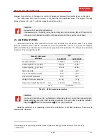
The


following


relationship


is


valid


for


the


calculation


of


a


level


at


the


output


of


the


receiving


antenna,


i.e.,


at


the


input


of


the


microwave


receiver:


P

in

[dBm]


=


P

vys

[dBm]


+


G

antV

[dB]


+


G

antP

[dB]


A

0

[dB]


where:


P

vys

[dBm]


is


the


transmitted


output


of


the


opposite


station


G

antV

[dB]


is


the


transmitting


antenna


gain


G

antV

[dB]


is


the


receiving


antenna


gain


A

0

[dB]


is


the


free


environment


attenuation


The


following


relationship


is


valid


for


the


attenuation


of


free


environment


during


good


climatic


conditions


(without


rain


and


fog):


A

0

[dB]


=


92.44


+


20


log(


d[km]


f[GHz]


)


where:


d[km]


distance


between


antennas


f[GHz]


used


frequency.


The


calculated


values


P

in


can


be


compared


with


the


values


measured


by


using


the


RSSI


calibration


graph,


or


by


direct


reading


of


the


values


given


by


the


monitoring


program.


If


the


constructed


connection


has


a


partially


disturbed


first


Fresnel


zone


then


the


attenuation


due


to


the


disturbance


cannot


be


higher


than

 ‐

6


dB


in


comparison


with


a


free


path.


The


optical


visibility


along


the


antenna


axis


has


to


be


maintained


in


any


case.


In


the


opposite


case


retranslation


would


have


to


be


used,


and


the


critical


spot


would


have


to


be


circumvented.


The


additional


attenuation


of


the


path


given


by


the


disturbance


of


the


1st


Fresnel


zone


by


a


single


terrain


obstacle


with


a


sharp


peak


is


represented


by


the


graph


(figure


28).


The


graph


shows


the


relative


height


of


the


obstacle


z


related


to


the


ellipsoid


radius


of


the


1st


Fresnel


zone.


The


value


z


=


0


represents


the


edge


that


touches


the


optical


connection,


i.e.,


covering


of


50%


of


the


ellipsoid


of


the


1st


Fresnel


zone.


Summary of Contents for ZENITH 80

Page 1: ...Microwave data link ZENITH 80 Installation and operation manual Document version 1 2 Published 15 4 2011 Last modification 08 01 2014 www alcoma com...

Page 2: ...ION OF OPTICAL CONNECTOR MOLEX 106059 31 3 13 BEFORE PUTTING THE RADIO LINK INTO OPERATION 32 3 14 ACCESSORIES 32 4 SETTING OF THE RADIO LINK AND ITS COMMISSIONING 34 4 1 POINTING OF RADIO RELAY LINK...

Page 3: ...ith Health Canada s Safety Code The installer of this device should ensure that RF radiation is not emitted in excess of the Health Canada s requirement Information can be obtained at http www hc sc g...

Page 4: ...uctions can cause damage to the equipment TIME EXPIRATION Link is time expired Date of expiration is marked on ODU in invoice and in dagnostic system ASD Client menu Supervisor Identification Local Re...

Page 5: ...oor ODU unit protected terminal box ALS1 GEth or ALS1 2GEth and the appropriate cables The link can be supervised by the ASD Client program through a web interface hyperterminal or SNMP protocol Ver 1...

Page 6: ...in the further text ODU can be connected to the microwave parabolic antennas of the types ALCOMA AL1 80 APR 0 35 m AL2 80 APR 0 65 m These antennas are standard equipped by icing protection radome fo...

Page 7: ...th of the link cable and the cable that brings data into the protected terminal box can be max 100 m long for the 100Mb s Ethernet for the Ethernet speed of 1000 Mb s it can be max 90 m long These len...

Page 8: ...ly protected terminal box marked ALS1 GEth 121 516 29 or ALS1 2GEth 121 516 30 for ZENITH 80 link There is danger of equipment damage in case using other terminal box MW Power suply Motherboard Line 3...

Page 9: ...are two different concepts of ZENITH 80 link output power regulation concept 1 The basic possibility is to set output power from maximum 20 dBm in steps of 1 dB and 20 dB range with keeping its time...

Page 10: ...th may be used with ALxxF MP165 ALxxF MP360 and and ZENITH 80 links see ODU sticker Protected terminal boxes are marked as ALS1 GEth 121 516 29 and ALS2 GEth 121 516 30 ALS1x should be mounted to DIN...

Page 11: ...r ends with the socket type 1777989 Phoenix 0395340002 Molex Type designation corresponds to the Phoenix Molex catalogue RJ45 connectors for user line input User lines 2 and 3 Wiring Pins Description...

Page 12: ...ox KRONE for the line 2 Cutting box Krone for the line 3 Power Line 2 contains power feeding Connector is wired as a mirror of ODU connector The marking of cable conductors Power feeding Wiring Pins D...

Page 13: ...2 3 Indikace Board Protected terminal box LED Abbreviation Meaning G POWER Power ON indication of the radio station being switched on 2 2 4 Cables in KRONE cutting boxes Figure 5 Cable wiring in ALS1...

Page 14: ...diagnostics of the link ODU can be attached to AL1 80 APR and AL2 80 APR antennas by four latches Feeder is connected to parabola Antennas stay pointed when ODU must be dismounted User terminal space...

Page 15: ...e does not consider the active functions AUTO MDIX Table 4 The outdoor unit cutting box KRONE for the line 2 Cutting box Krone for the line 3 power The marking of cable conductors Power feeding Wiring...

Page 16: ...Microwave radio relay link ZENITH 80 16 52 1 2 Figure 7 User space ODU 1xGEth Figure 8 User space ODU 2xGEth Indication LED Description Meaning...

Page 17: ...osition Description 0 Normal station operation 1 Pointing 2 F Reserve not used yet Table 7 Description of functions of the rotary switch in the ODU user space The rotary switch in the position Pointin...

Page 18: ...tical visibility Place for attachment of antenna with ODU A place for the protected terminal box ALS1x Path to lay the ODU ALS1x connection cable Guaranteed direct visibility is not always sufficient...

Page 19: ...at you can see the opposite side does not mean that you can set up a quality radio link 3 3 PLACEMENT OF THE ANTENNA ON A SUPPORT CONSTRUCTION The antenna of radio link must be placed sufficiently far...

Page 20: ...6 0 9 1 2 1 3 1 4 1 4 1 4 1 4 1 5 1 5 1 8 2 1 2 3 2 5 Table 8 Recommended antenna placements considering a distance from an obstacle 1 1 Table values correspond to an average antenna size and normal c...

Page 21: ...TENNA SYSTEMS Station antenna systems are attached to a vertical steel pipe that is a part of a girder mast structure or to other steel constructions firmly connected to the building on which the stat...

Page 22: ...ZENITH 80 22 52 1 2 3 5 1 AL1 80 APR AL2 80 APR antenna Figure 13 ODU attachment to AL1 80 APR AL2 80 APR antenna Feeder is integrated in antenna ODU is attached to antenna by four latches for easier...

Page 23: ...ed without affecting the link pointing direction For easy pulling up of ODU with the antenna to a mast or a support pipe lifting lug that is approx above the center of gravity of this system can be us...

Page 24: ...e marked hole at the bottom of ODU that is placed under the connection cable grommet The antenna system grounding points of AL1 80 APR a AL2 80 APR antennas are common with those of ODU This whole equ...

Page 25: ...ion of the whole link Feeder and antenna are one whole Attache the feeder to the antenna according to the following steps when delivered separately Check that O ring is slipped on feeder Attach the fe...

Page 26: ...ith branch line Retransmission LX SX with 2 branch lines Retransmission with 4 branch lines 1 1 TP 1 1 LX SX Figure 17 Typical ODU wiring LINE3 LINE2 LINE4 POWER ALS1x 48V DC LINE3 LINE2 LINE4 POWER L...

Page 27: ...of this bolt in open position enables locking of the lid in any position Since the user buses are located in the inside hermetically enclosed space of the box the lid is provided with a gasket To pro...

Page 28: ...met are placed over the cable The top 25 cm of PVC cable cover from the cable end will be removed The silk guiding thread also needs to be cut The shielding has to be coAPRessed a little and the condu...

Page 29: ...ponding after installation tightness of the grommet must be ensured for these customer selected cables too CAUTION It is not allowed to unscrew the grommet from the ODU wall under any circumstances Th...

Page 30: ...nm 1000Base BX WDM Singlemode TX 1310 nm RX 1550 nm 1000Base BX WDM Singlemode TX 1550 nm RX 1310 nm Figure 21 Optional SFP modules Modules can be installed only to ODUs equipped with special connecto...

Page 31: ...activator to protective layer of the fibre 7 Slip the connector body up to the optical fibre case 8 Shift crimp ring over kevlar and connector body back end Oring is on the right when looking to the...

Page 32: ...14 ACCESSORIES Based on customer wishes we can deliver all accessories necessary for installation and service of the radio relay links ZENITH 80 interconnect cables KRONE pusher knife Lockable 19 stan...

Page 33: ...brown White green Green Blue Brown White orange Orange White blue White brown White green Green Blue Brown White orange Orange White blue White brown White green Green Blue Brown LINE2 LINE3 Power T 2...

Page 34: ...cabinet may not be placed near heat water dust or vibration sources etc The ALCOMA ODU units do not contain any adjustment or tuning elements that would have to be modified during commissioning by cu...

Page 35: ...g procedure and wait when meteorological conditions rain snow can have influence on sudden Rx signal level changes Pointing means turning antennas in both directions to achieve the best Rx signal leve...

Page 36: ...position Base tone of acoustic signalization sounds which by its pitch not intensity corresponds to the strength of received signal A deep base tone sounds when the unit does not receive any signal or...

Page 37: ...t unnecessary play that would later cause a loss of exact direction after tightening While turning fine horizontal pointing nuts of you can find the main lobe on the connected DC voltmeter and in the...

Page 38: ...good to calculate the signal level that should be measured The maximum allowed deviation between the calculated and measured signal levels is 3 dB If the negative deviation is higher the connection n...

Page 39: ...own for horizontal polarization ant to the side for vertical polarization see figure 27 Attach ODU to the antenna by 4 latches Right hand or left hand ODU installation can be determined according to t...

Page 40: ...with the values measured by using the RSSI calibration graph or by direct reading of the values given by the monitoring program If the constructed connection has a partially disturbed first Fresnel z...

Page 41: ...rnet where both user data and the monitoring data are transmitted If this connection is not possible the monitoring PC with installed and running ASD program can be connected directly to ODU through a...

Page 42: ...nd this connection is only an emergency solution acceptable for a short time For service purposes Alcoma delivers a cable ended on one side by the Cannon 9F connector and on the other by the Cannon 9M...

Page 43: ...nfiguration etc The monitoring system enables diagnostics of the radio links and both local and remote ends of the connection The monitoring system is not necessary for the link transfer function itse...

Page 44: ...onstrable inspection of the safe product condition This inspection must be recorded and signed by an authorized person This record must be handed together with the repaired product to the user The ins...

Page 45: ...g to protection protection against injury by electric current is based on the connection to a SELV supply with the voltage no higher than SELV According to the standards regular inspections and checks...

Page 46: ...MHz Channel number ECC REC Recomended channel pairs MHz Transmitter frequency MHz 1 71 250 00 1 81 250 00 2 71 500 00 2 81 500 00 3 71 750 00 3 81 750 00 4 72 000 00 4 82 000 00 5 72 250 00 5 82 250...

Page 47: ...basic version 20 dBm Transmitter spectrum mask ETSI 301 751 Typical threshold sensitivity during BER 10 6 max values are by 3 dB higher than typical values 63 dBm Ethernet user interface 10 100 1000B...

Page 48: ...hanges i e elastic deformation occur up to the wind speed of 56 m s 200 km h Permanent deformation can occur above this threshold however without damage to ODU itself The protected terminal box is int...

Page 49: ...46 dBi 51 dBi Antenna gain Gant 83 5 GHz 47 dBi 52 dBi Main lobe 3 dB 0 4 0 2 Fine horizontal adjustment 20 20 Fine vertical adjustment 20 20 Weight of compact antennas 8 1 kg 11 kg Diameter of instal...

Page 50: ...radio relay link ZENITH 80 50 52 1 2 8 MAIN EQUIPMENT DIMENSIONS 8 1 ODU OUTDOOR UNIT 309 255 175 Figure 31 Main ODU dimensions 8 2 PROTECTED TERMINAL BOX 1 63 44 1 47 1 38 25 Figure 32 Main dimension...

Page 51: ...ZENITH 80 51 52 1 2 32 44 466 441 482 25 1 38 1 63 Figure 33 Main dimensions of 3 assembled terminal boxes ALS1x to 19 rack 8 3 ODU WITH ANTENNA 215 374 493 569 O371 Figure 34 Main dimensions of stati...

Page 52: ...Microwave radio relay link ZENITH 80 52 52 1 2 308 745 375 528 O730 Figure 35 Main dimensions of station with AL2 80 APR antenna...

Page 53: ...nna 37 Pointing 38 Radiation diagram 38 The RSSI calibration graph 39 Setting of polarization for ZENITH 80 39 The approximation of additional attenuation behind an obstacle 41 The direct connection o...

Page 54: ...ALCOMA spol s r o Vin ova 11 106 00 Praha 10 Czech Republic E mail alcoma alcoma cz www alcoma com...

Reviews: