Microwave
radio
relay
link
ZENITH
80
19/52
1.2
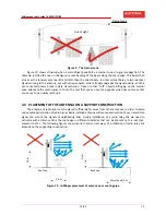
Figure
9
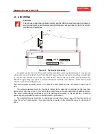
The
Fresnel
zone
Figure
10
shows
situation
when
a
solid
object
penetrates
a
Fresnel
zone
of
signal
propagation.
The
obstacle,
just
like
the
one
on
the
figure,
causes
bending
of
the
beam
along
the
sharp
edge.
This
beam
then
arrives
at
the
receiver
antenna
little
bit
later
than
the
direct
beam.
In
other
words
there
are
two
identical
signals
coming
to
the
antenna,
but
with
various
phases,
which
strongly
degrades
the
signal
quality;
and
this
can
cause
temporary
break
in
data
transmission.
Trees
or
other
“soft”
objects
infringing
on
the
Fresnel
zone
attenuate
the
radio
signal.
In
short:
The
fact
that
you
can
see
the
opposite
side
does
not
mean
that
you
can
set
up
a
quality
radio
link.
3.3
PLACEMENT
OF
THE
ANTENNA
ON
A
SUPPORT
CONSTRUCTION
The
antenna
of
radio
link
must
be
placed
sufficiently
far
away
from
other
antennas,
in
order
to
avoid
undesirable
perturbation
of
radio
signal.
Badly
installed
antenna
will
cause
deterioration
of
our
transmitted
signal
and
also
of
the
signals
of
neighboring
links.
During
installation
of
a
radio
relay
link
we
need
to
calculate
with
a
distance
from
the
roof
edge
or
different
obstacles
that
can
be
present
on
the
roof
(A/C,
elevator
shaft…).
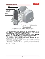
The
following
figures
show
incorrect
and
correct
ways
of
installation
of
radio
relay
link
antenna
on
the
supporting
construction.
Figure
10
IAPRoper
placement
of
antenna
on
mounting
pipe
Fresnel
zone
Line
of
sight
1,4
m
0,3
m
Roof
line
Roof
line
1,3
m
More
than
0,3
m

