


Microwave
radio
relay
link
ZENITH
80
21/52
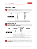
1.2
3.4
LOCAL
FREQUENCY
COORDINATION
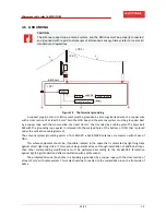
The
following
picture
shows
possible
local
frequency
coordination
in
unlicensed/uncoordinated
frequency
band.
Placement
of
antennas
is
shown
only
as
one
of
possible
recommendations.
If
there
is
more
80
GHz
frequency
band
radio
links
in
one
location,
polarization,
or
possibly
link
channel
numbers
must
be
selected
to
eliminate
undesirable
interference.
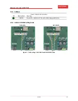
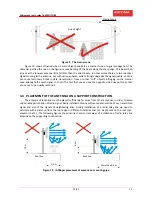
The
following
figure
12
shows
possible
polarization
combinations.
Figure
12
The
examples
of
channel
and
polarization
usage
in
case
of
more
links
in
one
location
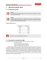
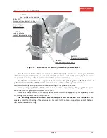
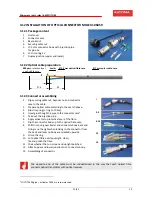
3.5
INSTALLATION
OF
THE
ANTENNA
SYSTEMS
Station
antenna
systems
are
attached
to
a
vertical
steel
pipe
that
is
a
part
of
a
girder
mast
structure,
or
to
other
steel
constructions
firmly
connected
to
the
building,
on
which
the
station
is
being
installed.
Diameters
of
supporting
pipes
are
set
by
the
table
15
on
the
page
49.
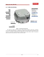
The
antenna
unit
may
not
be
installed
on
building
equipment
that
have
not
been
set
or
modified
for
this
purpose.
Minimum
1
m
(shorter
distance
is
possible
if
proper
functionality
is
verified)
ODU
A
Tx
polarization:
horizontal
ODU
B
Tx
polarization:
horizontal
ODU
A
Tx
polarization:
vertical
ODU
B
Tx
polarization:
vertical
Minimum
1
m
(shorter
distance
is
possible
if
proper
functionality
is
verified)
ODU
A
Tx
polarization:
horizontal
ODU
B
Tx
polarization:
horizontal
ODU
A
Tx
polarization:
vertical
ODU
B
Tx
polarization:
vertical


