background image


Mainboard K8X250 

 6 

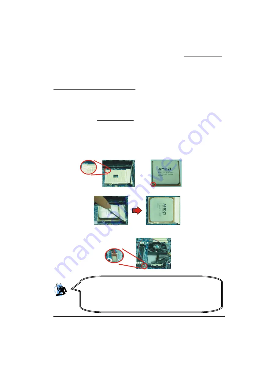
Diagonally 
Cut-corner

Gold triangle

Hardware Installation 

This section will assist you quickly in installing your system hardware. Wear a wrist ground strap 

before handling components. Electrostatic discharge may damage your system components. 

CPU Processor Installation 

This mainboard supports AMD Athlon

TM

 64/ Sempron

TM

 processor using a Socket 754. Before 

building your system, it is recommended that visit the AMD website for the detailed processor 

installation procedures. (http://www.amd.com)  

CPU Socket 754 Configuration Steps: 

1. Locate the CPU socket on your mainboard and nudge the locking lever away from the socket. 
Then lift the lever to a 90-degree angle. 
2. On the socket, locate the corner which has the “diagonally cut-corner” on the rectangular 
shaped pattern of pinholes (see diagram below-left). Match that corner with the “gold triangle” 

on the CPU (see diagram below-right) and lower the CPU onto the socket. The bottom of the 

CPU should be flush with the face of the socket. 


3. Lower the lever until it snaps back into position. This will lock down the CPU.   


4. Smear thermal grease on top of the CPU. Lower the CPU fan onto the CPU and use the 

clasps on the fan to attach it to the socket. Finally, extend the power cable from the fan and 
insert it onto the “CPUFAN” adapter. 


Attention 

DO NOT touch the CPU pins in case they are damaged. Also, make sure 

that you have completed all installation steps before powered on the 
system. Finally, double-check that the cooling fan is properly installed 

and the CPU fan power cord is securely attached, in case your CPU and 
other sensitive components are damaged because of high temperatures. 

Summary of Contents for K8X250

Page 1: ...cument are registered by their respective owner Disclaimer We make no warranty of any kind with regard to the content of this user s manual The content is subject to change without notice and we will not be responsible for any mistakes found in this user s manual All the brand and product names are trademarks of their respective companies FCC Compliance Statement This equipment has been tested and...

Page 2: ...a grounded wrist strap when working with the system 0 Do not touch any IC chip lead connector or other components 0 Always unplug the AC power when you install or remove any device on the mainboard or when confuguring pins and switches Packing List K8X250 mainboard FDD Cable HDD Cable I O Bracket for ATX case USB 2 0 cable optional SPDIF card optional SATA Power Cord Optional SATA Cable Optional M...

Page 3: ...0 K8X250 nVIDIA nForce3 250 Support Socket 754 AMD AthlonTM 64 SempronTM Processor User Manual Dimensions ATX form factor z 205mm x 305mm W x L Operating System z Windows 2000 XP ...

Page 4: ...ATION 6 CPU Processor Installation 6 Memory Installation 7 Back Panel Configuration 8 Connectors 10 Front Panel Headers 11 Headers Jumpers 12 Audio Configuration 15 Slots 16 Power Supply Attachments 16 CHAPTER 2 BIOS SETUP 17 CHAPTER 3 TROUBLESHOOTING 20 APPENDIX I SUPER 5 1 CHANNEL AUDIO EFFECT SETUP 23 APPENDIX II RAID SETUP 24 ...

Page 5: ...MB 2 88MB drives This mainboard has onboard Serial ATA function with two SATA connectors and are compatible with the SATA 1 0 specification The SATA interface provides up to 150 Mbps and supports with RAID 0 1 0 1 JBOD mode See Appendix II There is a maximum of eight USB2 0 1 1 ports that can be set up on this mainboard The onboard AC 97 sound codec supports high quality performance 6 channel audi...

Page 6: ... Two 184 pin DIMM sockets support a total memory capacity of 2GB z Supports DDR400 PC3200 DDR333 PC2700 DDR266 PC2100 DDR200 PC1600 SDRAM Slots z One 8x AGP slot z Five 32 bit PCI slot z One CNR slot optional FDC Connector z One floppy drive disk connector supports a maximum of two FDDs to be set up z Supports 360Kb 720Kb 1 2Mb 1 44Mb 2 88Mb IDE Connector z Two IDE connectors support a maximum of ...

Page 7: ...ps Digital Interfaces S PDIF function Onboard LAN Chip z 10 100 Mbps Ethernet LAN supported Onboard I O facilities z One multi mode Parallel Port is capable of supporting the following 1 Standard Bi direction Parallel Port 2 Enhanced Parallel Port EPP 3 Extended Capabilities Port ECP z Two serial port The COM3 serial port is optional z One SPDIF out port z One PS 2 mouse port and one PS 2 keyboard...

Page 8: ...orts Phoenix Award BIOS power management functionality z Supports system wake from power saving mode by keyboard or mouse Hardware Monitor Function z Monitor CPU Chassis Fan Speed z Monitor CPU and system temperature z Monitor system voltages ...

Page 9: ...V1 1 JAUDIO1 1 JCDIN1 1 JSPDIF_OUT optional 1 7 JSATA5 1 7 JSATA4 1 2 23 24 JPANEL1 1 1 JUSBV3 JUSB1 1 1 1 JSF AN1 JCMOS1 JCI1 1 JCFAN1 DD R1 DDR 2 1 JUSB2 1 JCOM2 JCOM 3 JCOM 1 LAN 1 JCDIN2 optional Codec CNR JSPDIF_IN optional 1 1 JUSBV1 Note 1 stands for pin 1 Note 2 JCOM3 is for optional ...

Page 10: ...has the diagonally cut corner on the rectangular shaped pattern of pinholes see diagram below left Match that corner with the gold triangle on the CPU see diagram below right and lower the CPU onto the socket The bottom of the CPU should be flush with the face of the socket 3 Lower the lever until it snaps back into position This will lock down the CPU 4 Smear thermal grease on top of the CPU Lowe...

Page 11: ...he K8X250 provides two 184 pin DIMM Dual In Line Memory Module sockets which support to insert DDR400 PC3200 DDR333 PC2700 DDR266 PC2100 DDR200 PC1600 SDRAMs and a total memory capacity of 2 GB Memory Setup Steps The following instructions explain how to install memories onto the DIMM sockets for this mainboard 1 Pull the white plastic tabs at both ends of the socket away Attention You can avoid d...

Page 12: ...memory vertically into the socket and press firmly by using both thumbs until the memory snaps into place 4 Repeat steps 1 2 3 for the remaining memory and DIMM sockets setup Back Panel Configuration The pictures shown above are for reference only The actual installation procedures may vary depending on the product you received ...

Page 13: ...e serial port COM1 and COM3 optional on the back panel and are used to attach mice modems and other peripheral devices USB LAN Ports JUSB3 JUSBLAN1 There are four USB 2 0 1 1 ports on the back panel These USB ports are used to attach with USB devices such as keyboard mice and other USB supported devices There is also a 10 100 Mbps Ethernet LAN port that you can attach directly to a network cable P...

Page 14: ...ecifications You can attach a maximum of two floppy disk drives using a FDD ribbon cable Hard disk drive Connectors The mainboard provides two IDE connectors that support PIO mode 0 4 Bus Master and Ultra DMA 33 66 100 133 specifications You can attach a maximum of four IDE devices such as hard disk drive HDD CD ROM DVD ROM and so on using the IDE ribbon cables Primary IDE Connector IDE1 There are...

Page 15: ...OFF 17 N A 18 Key 19 N A 20 N A 21 5V 22 Ground 23 IRTX IrDA IR 24 IRRX IrDA IR Speaker Header Green SPK A speaker cable on your case front panel can be attached to this header When you reboot the computer this speaker will issue a short audible beep If there are problems during the Power On Self Test the system will issue an irregular pattern of audible beeps through this speaker Pin Assignment P...

Page 16: ...ton Header Black ON OFF This header can be attached to a power switch cable on your case front panel You can turn your system on or off by pressing the button attached to this power switch cable IrDA Header Blue IR Attach the IrDA cord of the case front case onto this header then you can transfer the data through this function Headers Jumpers Case Open Warning Header JCI1 This header is used to wa...

Page 17: ...epending on which USB port that the USB device is attached to Note Close stands for putting a jumper cap onto two header pins Pin Assignment Pin Assignment 1 5V fused 2 5V fused 3 USB 4 USB 5 USB 6 USB 7 Ground 8 Ground 1 2 10 JUSB1 JUSB2 9 Key 10 N A JUSBV1 3 Assignment Assignment 1 Pin 1 2 Close 5V JUSBV1 5V for JUSB3 JUSBV3 5V for JUSB1 2 1 Pin 2 3 Close 5VSB JUSBV1 JUSB3 is powered with 5V sta...

Page 18: ... standby voltage Note Close stands for putting a jumper cap onto two header pins Clear CMOS Jumper JCMOS1 The Clear CMOS function is used when you are unable boot your system and need to reset the BIOS settings CMOS settings back to the manufacturer s original settings This is also a way to reset the system password if you have forgotten it JCMOS1 Assignment Pin 1 2 Close Normal Defult Pin 2 3 Clo...

Page 19: ...in center 2 Ground 3 Mic power Bass 4 Audio power 5 Right line out Speaker out right 6 Right line out Speaker out right 7 Reserved 8 Key 9 Left line out Speaker out left 10 Left line out Speaker out left 11 Right line in Rear speaker right 12 Right line in Rear speaker right 13 Left line in Rear speaker left 14 Left line in Rear speaker left CD ROM Audio In Connector JCDIN1 JCDIN2 optional The JCD...

Page 20: ... expansion cards Communication Network Riser Slot CNR1 optional The CNR stands for Communication Network Riser which is an open Industry Standard Architecture and supports modem only Power Supply Attachments ATX Power Connector JATXPWR1 PATXPWR2 This mainboard provides two power connectors a 20 pin JATXPWR1 connector and a 4 pin PATXPWR2 connector You must use a power supply that has both of these...

Page 21: ...m s ROM is a custom version of an industry standard BIOS This means that it supports the BIOS of Intel based processors This version of the PHOENIX AWARD TM BIOS includes additional features such as virus and password protection as well as special configurations for fine tuning the system chipset The defaults for the BIOS values contained in this document may vary slightly with the version install...

Page 22: ...eds Keystroke Function Up arrow Move to previous option Down arrow Move to next option Left arrow Move to the option on the left menu bar Right arrow Move to the option on the right menu bar Esc Main Menu Quit without saving changes Submenus Exit Current page to the next higher level menu Move Enter Move to the option you desire PgUp key Increase the numeric value or enter changes PgDn key Decreas...

Page 23: ...in its best performance configurations Set Supervisor Password Set change or disable password It allows you to limit access to the system and or BIOS setup Set User Password Set change or disable password It allows you to limit access to the system Save Exit Setup Save CMOS value settings to CMOS and exit setup Exit Without Saving Abandon all CMOS value changes and exit setup ...

Page 24: ...ive is active but system seems hung Causes Memory DIMM is partially dislodged from the slot on the mainboard Solutions 1 Power Down 2 Using even pressure on both ends of the DIMM press down firmly until the module snaps into place Problem 3 System does not boot from the hard disk drive but can be booted from the CD ROM drive Causes 1 Connector between hard drive and system board unplugged 2 Damage...

Page 25: ...data Then performs low level format partition and then a high level format the hard drive Re install all saved data when completed Problem 6 Screen message says Invalid Configuration or CMOS Failure Causes Incorrect information entered into the BIOS setup program Solutions Review system s equipment Reconfigure the system Problem 7 The Screen is blank Causes No power to monitor Solutions Check the ...

Page 26: ...nected properly Solutions Check hard drive cable Problem 13 Cannot boot the system after installing a second hard drive Causes 1 Master slave jumpers not set correctly 2 Hard drives are not compatible different manufacturers Solutions 1 Set master slave jumpers correctly 2 Run SETUP program and select the correct drive types Call drive manufacturers for possible compatibility problems with other d...

Page 27: ...rround audio output To use this function you have to install the Realtek Audio Driver in the bonus Pack CD see Software Installation section You must also use audio applications supporting 5 1 Channel audio effects See the audio Port Connectors in the Hardware Installation section for a description of the output connectors when Super 5 1 Channel Audio Effects are installed Speaker Test Make sure t...

Page 28: ...e redundant disks This redundancy provides fault tolerant protection from a single disk failure If a read write failure occurs on one drive the system can still read and write data using the other drive The minimum number of drives for a RAID 1 configuration is 2 You are required to use an even number of drives Disk Striped Mirroring RAID 0 1 This mode combines both the performance benefits of RAI...

Page 29: ...es listed on the Define a New Array screen with the physical drives attached to the connectors on the mainboard This becomes important when identifying drives that need to be replaced or changed Channel Controller Master Slave Located here are 3 identifiers separated by periods These identifiers represent the Channel Controller and Master Slave ID for a drive With these identifiers you can associa...

Page 30: ... JBOD Then press Enter Next Tab over to the Striping Block option and press Enter A pop menu will display as shown below With this option you can manually select the striping block size for your array This option will affect data access performance We recommend that you to select Optimal option for automatic configuration Press Enter Attention The Loc and Disk Model Name located on this screen ref...

Page 31: ...to the Array Disks section You can use the left arrow key to reverse your selection After you finish selecting all your disks Press F7 A confirmation message will display as shown below Then press Y to complete the RAID array creation After the array has been successfully created the Array List screen will display as shown below left You can press the Enter key to view the RAID details in the Arra...

Page 32: ...ray You can delete an existing array on the Array Detail screen Press the D key A warning confirmation message will display as shown below Press Y to confirm After the array is successfully deleted the screen will display as shown below ...

Page 33: ...ed Array you must copy the NvRaidMan exe file from the bundled CD Driver to your C drive CD File Location Path D Driver nForce 4 24 IDE WIN2K or WINXP NvRaidMan exe To rebuild a mirrored array bring up the NVIDIA RAID Utility From the Array List screen select the array with the newly installed drive Then go to the Array Detail screen press Enter Then press the R key and use the up down arrow keys ...

Page 34: ...n the Windows Setup screen will prompt you with Press F6 if you need to install third party SCSI or RAID driver Press F6 2 Press s when setup asks if you want to specify an additional device Insert the floppy disk which includes the RAID Driver into the floppy drive Press Enter and select the appropriate OS device driver 3 Press Enter again to continue the setup process 4 Follow the setup instruct...

Reviews: