


Albalá Ingenieros | Manual
FRS3004C02
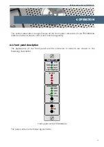
In the ADJUST box:
ZERO:
Red. These LEDs light up to indicate that the selected parameter is
set to its default value.
+/-:
Pushbuttons. These are used to increase or decrease the value being
configured.
4.2. Configuration from the front panel
Configuration from the front panel requires establishment of:
- The input for which the change will be made.
- The parameter to be configured.
- The value that said parameter should have.
Configuration is started with a short press of the SELECT button. This causes the Input 1
LED in the SDI INPUT box to light up. Successive short presses of the same button will
change the input whose LED then lights up. A sustained press of the SELECT button
validates the input selected and moves the module to a state where the parameter to be
modified can be chosen. This parameter is chosen with short presses of SELECT which
cycles through the choices. A sustained press will cause the input and parameter LEDs to
blink, indicating that the parameter value can be changed. This value is then modified
using the + and - buttons.
The + and - buttons can increase or decrease the configured value. A short press causes a
single unit change of the parameter, whereas a sustained press (longer than one second)
will cause coarse changes. The ZERO LED indicates that the selected value corresponds to
the default from calibration: no delay, gains of 1 for luminance and chrominance, no
offset in the black level. A sustained press of the SELECT button validates the value of the
parameter at that moment and stores it in EEPROM. The module then exits
configuration mode and the LEDs go back to displaying the status of the device.
The front panel programming routines have a timeout function and if no action is taken
for over one minute then the unit exits configuration mode and discards any changes
made.
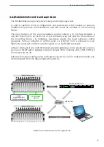
4.3. Functional description
The FRS3004C02 includes a module for synchronizing to the reference signal as well as
four identical sections for synchronizing and processing each input.
Each input signal is deserialized and if the data received is valid then it is stored in the
frame memory. The frame memory is read in sync with the reference signal while
respecting the delays programmed by the user. The following adjustments can be made
to the video signal: luminance gain, chrominance gain and black level. Furthermore, the
checksums of the modified SDI signal are calculated and EDH packets are inserted into
19
Summary of Contents for FRS3004C02
Page 2: ...FRS3004C02 ...
Page 4: ...FRS3004C02 ...
Page 7: ...Albalá Ingenieros Manual FRS3004C02 1 3 Block diagram 7 ...
Page 8: ...Albalá Ingenieros Manual FRS3004C02 FRS3004C02 8 ...
Page 10: ...Albalá Ingenieros Manual FRS3004C02 Approximate weight 350 g 10 ...
Page 16: ...Albalá Ingenieros Manual FRS3004C02 FRS3004C02 16 ...
Page 26: ...Albalá Ingenieros Manual FRS3004C02 FRS3004C02 26 ...
Page 28: ...Albalá Ingenieros Manual FRS3004C02 FRS3004C02 28 ...
Page 30: ...Albalá Ingenieros Manual FRS3004C02 FRS3004C02 30 ...


