43
42
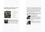
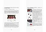
• always make sure that the wheel nuts are
loose and cross-tightened (a-c-d-b) (photo
A);
• lift the vehicle and remove all the wheel
nuts;
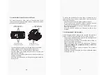
• remove the hub cap (photo B);
• the wheel can be removed and replaced;
• always use the same size and type of wheel
for all 4 wheels on the vehicle;
• use only 215/35-12" tyres with equivalent
PCD, CB and ET given by the Manufacturer;
• when fitting a new wheel, proceed in the
reverse order of the above procedure;
• insert the hub cap and tighten the wheel
nuts to a torque of 90Nm±5Nm;
• check the tightness of the wheel nuts after a few days of
driving.
7.6 ELECTRIC FUSE BOX POSITION
In the event of a malfunction in the electrical
system, it is advisable to check the fuses
available on board. In the event of a fault, it
is necessary to replace the damaged fuse
with one of the same amperages. In order
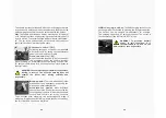
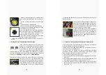
to understand if a fuse is damaged, it is necessary to analyse
the internal filament as shown in the following image, where
a
represents an
OK fuse and b represents a NOT OK fuse.
There are two types of fuse in the vehicle, those for the traction
part and those for the accessories. The
traction fuses can be found in compartment
11 on page 27 near the vehicle control inverter.
There are three sizes of fuse, a 5A beige fuse
protecting the controller, a 30A green fuse
protecting the battery charger, and a 350A fuse protecting the
battery supply.
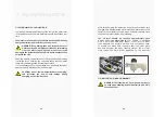
The version not fitted with lights (accessory)
has a fuse in the battery area, as shown in
the picture opposite. This fuse protects the
branch that feeds the USB socket; it has a
rating of 10A and is red in colour.
In the version equipped with headlights
(accessory), there are fuses to protect the
lighting system and the 12V produced by
the DC-DC converter (can be checked in
compartment 5 on page 28). Both fuses are
10A and red in colour.
7.7 ELECTROMAGNETIC BRAKE RELEASE
In an emergency, the electromagnetic brake can be released
manually (using the special kit supplied).
Place chocks under the wheels that are not raised to prevent
the vehicle from rolling forward.
All work must be carried out by authorised and qualified
personnel, having read and understood this manual, using
appropriate professional procedures and tools:
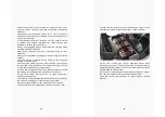
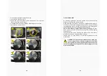
1. remove the inverter panel (photo C);
2. disconnect the brake electrically, by unplugging the connector
(photo D);
3. remove the plastic screw caps in each access hole using a 12
mm spanner or a slotted screwdriver (photos E - F);
4. screw the M5x30 screws provided in each hole to compress
the internal springs and allow the clutch disc to rotate freely
(photos G - H).
Summary of Contents for Crew
Page 1: ...WELCOME TO ALBA CREW...
Page 28: ...11 NOTES...
Page 29: ......
Page 30: ...www albamobility it Alba Mobility is part of TCN GROUP...


