

5
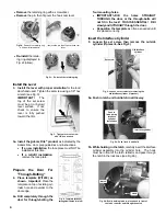
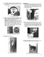
5c. The interface cylinder must be centered
and posi-
tioned flush with (or slightly below) the surface of the
door (see Fig. 7).
5d. With the interface cylinder HELD SECURELY in its
correct position, tighten the set screw
, securing the
interface cylinder to the lock (see Fig. 7a).
Important!
If the interface cylinder is not parallel to
the door after tightening the set screw, then you must
verify that the original Adams Rite
®
lock body was
originally installed correctly (installed square to the
door). Failure to ensure the interface cylinder is in-
stalled correctly could cause lock binding or improper
operation of the lock mechanism.
5e. Install
the latch face plate.
Install Lock
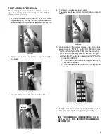
6. Install the DL lock onto the door
by aligning the two
posts on the front of the interface cylinder with the two
corresponding holes in the back of the DL lock. Lift the
tailpiece slightly to ensure the tailpiece enters the slot
of the interface cylinder.
6a. Secure the DL lock to the door
with four through-
door mounting screws and two door plates. Place a
door plate on top of a pair of mounting holes and
loosely
secure lock from the inside of the door. Snug
all four mounting screws before final tightening.
Do not
over-tighten.
6b.
Cover door plates
with decorative plate covers by
sliding them from top to bottom on door plates.
Fig. 7: Position the interface cylinder
Fig. 7a: Tighten the interface cylinder set screw
Fig. 9: Secure lock to door -- loosely at first
Door plate
Fig. 9a: Slide down to install decorative plate covers
Fig. 7b: Install the latch face plate
Fig. 8: Install lock onto the door