background image

AL-MEISTER ALM3220 Instruction Manual <Rev.2> 


Page 21 of 50 

4. INITIAL THREADING OF THE ALM3220 (cont’d) 


If the card and film to do exit the machine within 5 seconds 

STOP!

 Film could 

be accumulating within the machine. If this is allowed to continue damage to 
the machine will occur! 
If the threading card and film do not emerge from the discharge 

within 5 

seconds

 pull the threading back out of the nip and repeat the threading process 

at step 6. 

If the machine is not threaded properly damage will occur. 


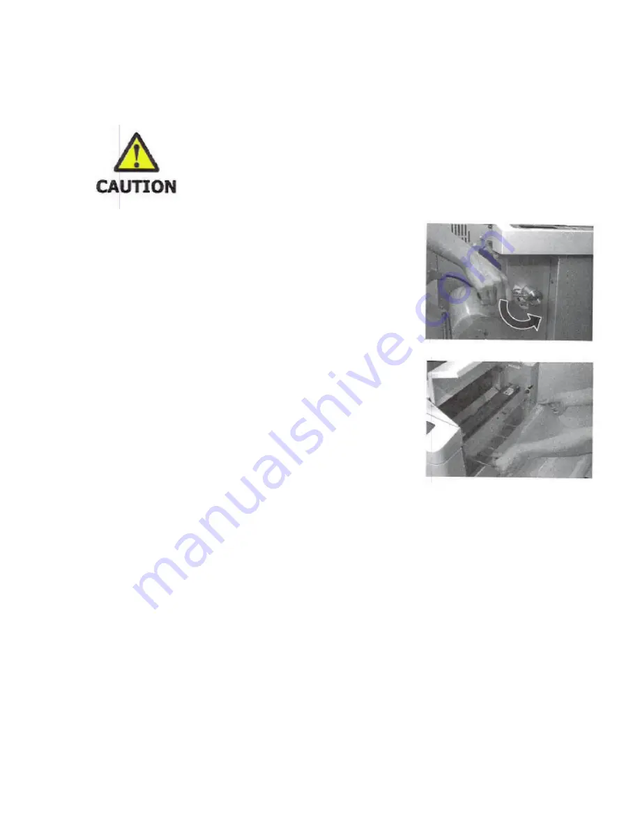
13. After the threading card and film combination emerge lower the 
Lamination Handle.  


14. Perform the remainder of this procedure with the machine warmed 
up (READY light on). Before running paper in the machine in automatic 
mode examine the lamination quality of the film. 


15. It is very important to look at the film as it exits the discharge. It should be well laminated (clear) and 
free of wrinkles. If wrinkles are observed adjust the tension knobs slightly on the film rolls. If the film is 
curled that could be an indication that the tension of one of the film rolls is tighter than the other. Film 
must exit the machine flat. If there is curl in manual mode (using the manual MOVE switch) there may 
be curl during automatic mode which will produce errors and possible damage to the machine. 


Summary of Contents for ALM3220

Page 1: ...uto Laminator Please read through this manual carefully before operation Please keep this manual and refer to it whenever necessary Ver 1 1 US Ver 2 by Brian Jennett 11 7 11 4 19 12 9 25 13 12 2 13 2 3 14 2 28 14 3 20 14 3 27 14 4 22 14 4 29 14 10 16 14 With inclusions from Ver 1 6 US 11 6 12 12 16 14 1 26 15 9 8 15 BJ ...

Page 2: ...CESSORIES 8 2 2 EXTERIOR VIEWS 9 2 3 INTERIOR VIEWS 10 2 4 OPERATION PANEL 11 2 5 LCD 12 2 6 OTHER OPERATION SWITCHES 14 3 INSTALLATION OF THE ALM3220 16 3 1 INSTALLING THE ALM3220 16 3 2 SET FEEDER TRAY 16 3 3 SET EXIT TRAY 16 3 4 SET WASTE COLLECTION BOX 17 3 5 CONNECT POWER CORD 17 4 INITIAL THREADING OF THE ALM3220 MANUAL MODE 18 5 AUTOMATIC OPERATION 26 5 1 WARM UP 26 5 2 SETTINGS 27 5 2 1 SE...

Page 3: ...PER 37 5 4 START OPERATION 38 5 5 ECO MODE Power Saving Mode 39 5 6 TERMINATE LAMINATION 39 6 LONG MODE 40 7 TROUBLESHOOTING ERROR MESSAGES 41 8 CLEANING AND LUBRICATING THE HEAT CHAMBERS 46 Instructions for DryLam product CLKIT Cleaning Kit 47 Instructions for DryLam product 01300 Maintenance Kit 47 9 SPECIFICATIONS 49 MAXIMUM PAPER THICKNESS 50 ...

Page 4: ...es possible injuries caused by tangling in a rotating machine part Amputation Warning Indicates possible serious injuries such as finger amputation Heat Warning Indicates the potential for injuries caused by extreme heat Don t Do Indicates unspecified acts that are forbidden Unplug immediately Indicates a dangerous situation Unplug the ALM3220 from the wall outlet and call for service These two di...

Page 5: ...riate power supply Always connect to AC120V Unstable voltage may cause electric shock fire or damage to the machine Always avoid using multiple outlet connections 2 Pay attention to the amperage Unless the amperage is enough it may cause fire or malfunction A dedicated circuit is highly recommended 3 Ensure a ground connection is correctly made to avoid any danger or electrical problems Do not alt...

Page 6: ...e easily accessible 3 IN AN EMERGENCY If a malfunction occurs switch off and or unplug immediately Contact your dealer or DryLam Tech Line Do not attempt to disassemble repair alter the machine yourself 4 OTHER CONSIDERATIONS In order to avoid serious personal injury or damage to the machine Do not use the machine for any other purposes than what it was designed for Do not put heavy items on the m...

Page 7: ...ent Wipe off the residue of detergent with a cloth soaked in water USEFUL INFORMATION FILM END This model has a function that gives caution that the film will end soon The final few feet of film has either black colored film or the black colored tape on the film Please note when doing continuous lamination that one or two sheets may be laminated with the black tape when film runs out Therefore in ...

Page 8: ...CTIONS 2 1 INCLUDED ACCESSORIES Please check all these components are included ALM3220 Auto Laminator Feeder Tray Feeder Tray Extension Exit Tray Power Cord Instruction Manual Waste Collection Box Stand Stand Assembly Instructions Tool for assembling Stand Screws for assembling Stand ...

Page 9: ... 1 Stand 10 Operation Lever 2 Stand Door 11 Upper Tension Controller 3 Waste Collection Box 12 Roll Film Cover 4 Lower Tension Controller 13 Trimmer Cover 5 Feed Adjustment Knob 14 Operation Panel 6 Feeder Tray 15 Exit Tray 7 Feeder Flex Paper Pressure Lever 16 Power Switch 8 Front Cover 17 AC Inlet 9 Feeder Cover ...

Page 10: ...ns 2 Feeder Tray Tray for paper 3 Feeder Roller Picks paper from feeder tray and aligns it at the Stopper Gate Rollers 4 Lower Film Roll 5 Stopper Gate Roller Corrects skew and feeds paper to lamination rollers 6 Heat Rollers Laminates upper and lower films with heat and pressure 7 Upper Film Roll 8 Cutter Unit Cuts front and back of the film leading and trailing edges 9 Trimmer Unit Cuts sides of...

Page 11: ...o reduce set value MODE Press to select MODE setting TEMP SPEED Press to select temperature or speed setting Press continuously to see the current temperature POWER LAMP Indicates the power is on READY LAMP Indicates that the set temperature has been achieved ECO LAMP Lights during the power saving mode ERROR LAMP Lights when an operation error occurs To aid in servicing note the error message tha...

Page 12: ...y heated If the machine has been properly threaded it is ready to be run in automatic mode To thread the machine see chapter 3 on page 13 2 TEMP indicates the set temperature in Fahrenheit 3 SPEED indicates the set speed in inches per minute 4 MARGIN indicates that the trimming and cutting is with without margin on the front and back leading and trailing edges of the laminated paper NOTE A margin ...

Page 13: ...on Manual Rev 2 Page 13 of 50 2 COMPONENT NAMES AND FUNCTIONS cont d Example SET COUNT MULTI laminates all the paper on the feeder tray 012 100 indicates the set number 100 and the number of processed sheets 12 have been finished ...

Page 14: ...k when a cutting error has occurred CAUTION Manual Switch works on any setting Account for all film going into the machine If film does not exit the discharge in less than 5 seconds STOP Film may be accumulating within the machine If this is allowed to continue damage to the machine will occur If you believe an excess amount of film has gone into the machine release the MOVE switch Raise the Lamin...

Page 15: ...nstruction Manual Rev 2 Page 15 of 50 After the film waste has been pulled from the discharge the machine is ready to be run in automatic mode Do NOT run the MOVE switch again unless CUT is performed immediately afterward ...

Page 16: ...ions regarding installation carefully 3 2 SET FEEDER TRAY Attach the tray by holding the feeder tray downward When you laminate materials in double letter and digital paper sizes set the extension tray on the feeder tray as shown 3 3 SET EXIT TRAY Attach the exit tray firmly in the holes Select upper or lower holes according to the film thickness 1 1 5mil 3 mil film thickness 2 4mil 5 mil film thi...

Page 17: ... 17 of 50 3 INSTALLATION OF THE ALM3220 cont d 3 4 SET WASTE COLLECTION BOX Open the door Set the waste collection box to the right so that there is no space between the box and the side 3 5 CONNECT POWER CORD Connect power cord to the machine firmly ...

Page 18: ...t levers Do not close the cover for the next step Always make sure that the levers are at the film set position when threading Otherwise the threading card will get caught on the trimmer blades Damage to the trimmer blades and jamming of film may occur 3 Open the covers in the following order Front Cover Feeder Cover and Film Cover Feeder Cover can only be opened when the front cover is open NOTE ...

Page 19: ...is incorrectly loaded adhesive may contact the heat chambers or rollers and cause damage 7 Raise the Lamination Handle to the OPEN position to separate the chambers and heat rollers 8 Pull the upper film off the roll Pull it down and over the upper rotating idler bar Bring the end of the film down until it just touches the lower film This should overlap both chambers by a few inches Bring the lowe...

Page 20: ... card fully inserted If this part of the threading is not performed correctly damage to the film guides on the Cutter Unit or other damage to the machine will result 10 Do NOT lower the Lamination handle at this time 11 Turn on the power switch if not already on NOTE During the following instructions i e during normal threading do not use the MOVE switch without the intent of moving film out of th...

Page 21: ...bination emerge lower the Lamination Handle 14 Perform the remainder of this procedure with the machine warmed up READY light on Before running paper in the machine in automatic mode examine the lamination quality of the film 15 It is very important to look at the film as it exits the discharge It should be well laminated clear and free of wrinkles If wrinkles are observed adjust the tension knobs...

Page 22: ...r than the upper controllers NOTE Single sided lamination Do not apply any tension to the upper or lower controllers Leave all 4 thumbscrews loose 17 When the laminator has warmed up and the READY light is on use the manual MOVE switch to run samples of film out of the laminator Observe these samples for clarity and freedom from wrinkles When all of the bubbles wrinkles and creases disappear from ...

Page 23: ... If the curl is less than 1 2 from the vertical plane there is no need to adjust If the curl is more than 1 2 to the lower side tighten the two upper tension controllers with half turn If the curl is more than 1 2 to the upper side loosen the two upper tension controllers with half turn 1 9 7 i n Within 1 2 inch 1 2inches Upper side Lower side Over 1 2 inch Lower side Over 1 2 in Upper side ...

Page 24: ...th use Too much tension will result in noise poor performance and increased wear on the chambers and other internal components Also as film rolls reduce in diameter due to use curling may begin If curling is allowed to continue film may curl back up inside the ALM3220 and causes jams and wraparounds If so re adjusting the tension controllers may be necessary Other results of poor tension controlle...

Page 25: ...o wrinkles or bubbles There is no curling in the film Film IS exiting the exit of the laminator the CUT button should now be pressed 21 Pull the film that is exiting the laminator 22 Set the Trimmer levers at their desired positions 23 Close all the covers in the order of Film Cover Feeder cover and Front Cover The machine is ready for automatic operation ...

Page 26: ... UP CAUTION Automatic mode should not be performed until the machine has been set up properly in Manual Mode See page 16 for details Connect the power cord to the wall socket Turn on the power switch This display appears for 3 seconds The POWER lamp lights and WARM UP appears on the screen ...

Page 27: ...OWN key to set temperature Temperature can be set in 10F increments The temperature display blinks Press TEMP SPEED key to confirm the temperature This table shows an example of temperature settings for different film and paper thicknesses It pays to experiment with different temperatures and speeds to achieve quality laminations Film thickness Copying paper Thicker paper 1 5mil 210F 40 min 220F 4...

Page 28: ... 2 SET SPEED Press TEMP SPEED key twice on the READY screen The default is set at 40 min Press UP or DOWN key to set speed The speed can be set by 4 min increments The speed display blinks Press TEMP SPEED key to confirm the speed Press TEMP SPEED key again to return to the previous display ...

Page 29: ...hout margin without laminated frame 2 With margin with laminated frame 3 Without margin without laminated frame 4 With margin with laminated frame 5 FILM setting position 1 and 2 for letter size and double letter size widths 3 and 4 for digital paper size widths NOTES When setting film always set the lever to 5 Position of Film Set Otherwise the threading card used for film setting may cause damag...

Page 30: ...AL MEISTER ALM3220 Instruction Manual Rev 2 Page 30 of 50 5 AUTOMATIC OPERATION cont d Lamination with laminated frame is shown as MARGIN ON Lamination without laminated frame is shown as MARGIN OFF ...

Page 31: ...I after power outage MARGIN SET Make cuts either with or without margin NOTE Defaults to MARGIN ON after power outage CUT ADJUST This parameter adjusts the cutting positions at the leading and trailing edges of each sheet NOTE These settings are retained in memory after a power outage TOTAL COUNT Total Count indicates the accumulated number of laminations since the RESET button was pushed NOTE Thi...

Page 32: ...ET COUNTER continued Select SET COUNT NOTE Defaults to MULTI after power outage Press UP or DOWN key to enter numeric values You can set up to 200 sheets Unspecified number of lamination is displayed as multi Press the MODE key one more time to confirm The display returns to the previous display ...

Page 33: ...ple 0 finished number 100 set value Lamination errors do not affect counting Example of setting multi When you select multi all the papers in the feeder tray will be laminated The default is set to multi 5 2 5 MARGIN SET Select MARGI N SET NOTE Defaults to MARGIN ON after power outage Press UP or DOWN key to turn MARGINS on or off Press MODE key to confirm ...

Page 34: ...s TEMP SPEED key and move the cursor to F or B F cutting position at the front end leading edge B cutting position at the back end trailing edge Set value using the UP Down buttons Adjustment can be done between 0 20 and 0 20 The more positive the number the more margin of film around the paper will remain The more negative the number the close to the paper the cutting will occur with the possibil...

Page 35: ...ressure Adjust lever from its current slot and adjust the amount of pressure as follows a If too many sheets are being fed at once adjust the lever upwards b If sheets are slow to enter or will not enter at all to the point that LAMINATION ERROR or other similar errors occur adjust the lever downward 2 Place the lever in the correct slot HINT If sheets are not being pulled off the tray completely ...

Page 36: ...et NOT drawn off the tray i e lever set too high than it is to have too many sheets drawn from the tray and entering the lamination section where jams can happen i e lever set too low In some cases it may be necessary to raise or lower the lever beyond the slot range provided These cases are rare but if necessary hold the lever in the optimal position with a magnet or adhesive tape ...

Page 37: ... to paper size Press the edge of the feeder tray downward Keep pressing it while loading paper Place paper in the feeder tray correctly The picture shows how to set letter Release your hand from the tray The spring action will push the paper upwards towards the feeder roller If necessary attach the extension tray for double letter and digital paper sizes ...

Page 38: ...THREAD THE ALM3220 COULD RESULT IN DAMAGE TO THE MACHINE Press the START key Operation starts Press STOP key during the operation to stop the lamination Lamination will stop when the process is done NOTE SINGLE SIDED LAMINATION ONLY Remove the carrier film from the backs of the sheets and discard FILM END Our exclusive AL ROLL Film has a special feature that allows the end of the film roll to be d...

Page 39: ...el have not been pressed in the past 15 minutes This does not apply to the MOVE switch A buzzer will sound 1 minute before entering ECO MODE ECO MODE will be deactivated by pressing any key The 15 minute timer then starts again 1 Current temperature 2 ECO MODE temperature goal 130F 5 6 TERMINATE LAMINATION 1 Make sure the lamination has finished 2 Turn off Power Switch Disconnect the power plug ...

Page 40: ... operation will continue non stop Therefore it is mandatory that an operator be present at all times to monitor operation If a malfunction occurs paper jam or otherwise and the operator does not switch off the POWER switch severe damage to the machine could occur if the machine continues to run unchecked In proportion to the length of paper being laminated there is the likelihood that paper will s...

Page 41: ...contact your dealer or DryLam Tech Line More than 1 sheet of paper is fed Paper is very thin Remove the paper Bring Paper Pressure Lever down by one notch Ruffle the papers well Flatten the papers Press RESET key Improper trimmer roller pressure tension Turn off the power Contact your dealer or DryLam Tech Line Do not dismantle the machine unless instructed Are cuts being made through paper and fi...

Page 42: ...et the Trimmer Levers to Position Of Film Set if they will not move leave them where they are 2 Use the Manual MOVE switch if necessary and 3 carefully move film out the back of the machine Then 4 cut the film using the manual CUT switch 5 Pull out any paper film from the back of the machine 6 Press RESET key to clear the error on the display and 7 try running in automatic mode again CAUTION Exces...

Page 43: ...position Open Front Cover Raise Lamination Lever to OPEN position There is a chance that damage could occur therefore Rethread the machine as per instructions Press RESET key to clear the error Roll film has run out Remove the empty film rolls Press RESET key Load new film rolls CAUTION Heat Chambers may be HOT Paper is stuck in the Feeder section Cutter Unit section or Discharge section Open Feed...

Page 44: ...n and laminate one sheet of paper Look at how the paper is centered within the film area If it is not centered adjust the paper tray adjustment screw or the paper tray guides to center the paper within the film area Set Trimmer levers as desired and run again Check if the trimmer adjustment levers are correctly set Adjust the trimmer adjustment levers It may be necessary to set the levers at posit...

Page 45: ...es one or more numbers are also given which represent the sensor which is being blocked 1 Feeder 2 Cutter 3 Discharge Turn the power off and back on again to activate the MOVE switch Carefully remove all sheets that are stuck within the machine Understand that use of the MOVE switch may cause damage to the machine if stuck film paper is not removed properly beforehand ...

Page 46: ... chambers will accumulate adhesive and dirt It is recommended that you periodically inspect them for adhesive build up Use DryLam Cleaning Kit part number CLKIT which contains Xenit Cleaner and a sponge for removal of any adhesive build up Other suggested solvents are Rubbing alcohol isopropyl 70 or higher Goof Off Acetone Poly Off ...

Page 47: ...ng Instructions for DryLam product 01300 Maintenance Kit After cleaning the chambers as described above it is HIGHLY recommended to use the DryLam Maintenance Kit DryLam part number 01300 Be certain the heat chambers are clean see above This product is not a cleaner or a solvent The Maintenance Kit includes Dry Film Lubricant without silicone and a microfiber cloth DO NOT SPRAY DRY FILM LUBRICANT ...

Page 48: ...s lubricant allows the film to slide over the chambers easily thus reducing the tension required This reduces noise and wear and will reduce linear scratches that may be seen in the film These products are available from your DryLam dealer or contact DryLam at 888 633 1975 ...

Page 49: ...minator 110 LBS Stand 48 5 LBS 158 LBS total Feeder capacity 200 pages copying paper Exit Tray capacity 200 pages copying paper laminated with 5mil film Finished Size utilizing slots in the Trimming Unit Letter 8 5 x 11 With Margin 8 74 X 11 24 Without Margin 8 38 X 10 88 Will process 200 sheets hour at this size Double Letter 11 x 17 With Margin 11 24 X 17 24 Without Margin 10 88 X 16 88 Digital ...

Page 50: ...m MIL COVER INDEX METRIC gsm 1 2 14 8 120 180 312 1 5 14 5 114 170 309 13 105 158 286 3 13 105 158 286 10 90 135 245 5 11 100 150 271 6 40 60 162 Table 1 For example looking at Table 1 above when laminating two sides of a sheet with 5 mil film the film itself is 10 mil s thick Hence paper stock can be no thicker than 6 mil 6 mil thickness equates to 40 cover or 60 index This is more of a limitatio...

Reviews: