background image

GB 13

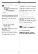
GB

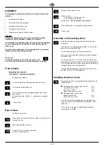
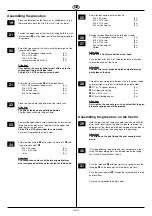
Assembling the grass box

Place the lower part of the frame on a suitable base (e.g. a

table) and push both the struts (6 mm Ø) into the bores.

Position the upper part of the frame, inserting both the struts

into the bores 

Œ

on the upper part of the frame provided for

this purpose.

Screw the upper part of the frame onto the lower part of the

frame on both sides.

M 6 x 35 hexagonal head screw

(4 x)

Ø 6 x Ø 18 shim

(4 x)

Ø 6 x Ø 12 shim 

(4 x)

selbstsichernde Mutter M 6

(4 x)

Attention!
Only tighten the nuts by hand to start with due to the
subsequent fixing of the box fabric.
Fit disk Ø 6 x Ø 18 under the screw head!

Screw the transverse tube 



onto the box frame.

M 6 x 45 hexagonal head screw

(2 x)

Ø 6 x Ø 12 shim 

(4 x)

Ø 6 curved shim 

(2 x)

M 6 self-locking nut

(2 x)

Place the frame onto the box base of the fabric sack.

Attention!
The ribs of the box base pointing upwards.

Clip the fabric sack onto the box frame.

Remove the upper frame screw connection and screw the

fitting flap of the fabric sack together with the upper and

lower part of the box frame.

Fit the Ø 6 x Ø 18 shim under the screw head.

Carry out this procedure on both sides.

Screw the box handle 

Œ

onto "superstructure left" 



and

"superstructure right" 

Ž

.

M 8 x 60 screw

(2 x)

Ø 8 x Ø 15 shim

(2 x)

shim

(2 x)

Attention!
The connection contours of the two superstructures
must correspond with the outer contour of the box lid.

Screw the box handle onto the box lid

M 6 x 20 screw

(2 x)

Ø 6 x Ø 12 shim

(2 x)

Ø 6 x Ø 18 shim

(2 x)

M 6 self-locking nut

(2 x)

Position the box lid and screw onto the box frame

M 6 x 40 hexagonal head screw

(5 x)

Ø 6 x Ø 18 shim

(5 x)

Ø 6 x Ø 12 shim

(5 x)

M 6 self-locking nut

(5 x)

Holder

(2 x)

Attention!
Fit the Ø 6 x 18 shim under the screw head.

Push the box strut (Ø 8 mm) through the base of the box

and the lower part of the frame.

Attention!
The box strut must protrude by the same distance on
both sides of the box.

Thread the gas spring onto the box strut in the order shown

and screw tight. Carry out this procedure on both sides.

Œ

Ø 12 x 13 spacer bushing

(2 x)



Gas-pressure spring

(2 x)

Ž

Ø 8 x Ø 15 shim

(2 x)



M 8 self-locking cap nut

(2 x)

Attention!
Only tighten the cap nuts to such an extent that the gas-
pressure springs can still be pivoted.

Assembling the grass box on the tractor

Hold the grass box by the box handle in one hand. With the

other hand - gently pressing onto the box lid - position the

upper part of the frame onto the box holding arms and push

forwards until the grass box engages in the bearings.

Attention!
The arrows on the box lid and the seat console must
match.

If the gap between the box lid and the seat console is too

large, the box holding arms can be adjusted by loosening

the screws in the directions shown.

Push the forkhead 

Œ

of the gas-pressure spring across the

fitting lug 



of the back wall until the bores are flush.

Push the securing bolts 

Ž

through the forkhead and the lug

and lock them.

Carry out this procedure on both sides.

19

21

21

20

26

27

22

23

24

25

28

29

30

31

Summary of Contents for 118240

Page 1: ...D GB 521 493 h 2004 Original Betriebsanleitung Translation of original user instructions...

Page 2: ...Hersteller siehe Typenschild Manufacturer see nameplate D GB...

Page 3: ...3...

Page 4: ...4...

Page 5: ...5...

Page 6: ...2 3 4 1 28 30 29 25 26 27 6 x 18 6 x 12 3 1 2 31 32 6...

Page 7: ...2 1 3 1 1 2 0 34 38 33 35 37 2 1 36a 36b I 0 2 1 39 7...

Page 8: ...1 2 3 41 2 1 1 42 44 43 ON OFF 1 1 2 40a 40b I 0 2 1 39 46 8...

Page 9: ...47 48 49 8 mm...

Page 10: ...Machen Sie sich vor der ersten Inbetriebnahme unbedingt mit dem Inhalt dieser Bedienungsanleitung vertraut Trotzdem k nnen von dem Ger t Gefahren ausgehen wenn es von ungen gend geschultem Per sonal...

Page 11: ...st erforderlich wenn z B durch Auffahren auf ein Hindernis der M her sofort zum Stehen kommt Motorwellensch den verbogene Messer usw 3 Hinweise zur Handhabung 3 1 Der Verbrennungsmotor darf nicht in g...

Page 12: ...nal Zubeh r zu verwenden Wir weisen darauf hin da wir nach dem Produkthaftungsgesetz f r Sch den die durch unser Ger t verursacht werden bei a unsachgem en Reparaturen welche nicht von unseren autoris...

Page 13: ...d verschieben bis das Hinterrad h rbar am Achsschenkel anschl gt Die Radachse schaut aus der Felge heraus O Ring 11 x 2 6 werkseitig montiert Sicherung der Passfeder 5 O Ring entfernen keine Wiederver...

Page 14: ...der Gasdruckfeder ber die Befestigungs lasche der R ckwand schieben bis die Bohrungen fluchten Sicherungsbolzen durch Gabelkopf und Lasche schie ben und verriegeln Diesen Arbeitsgang an beiden Seiten...

Page 15: ...auf dem Reifen ablesen 1PSI 0 07 bar Mit einer handels blichen Fu luftpumpe kann der Reifendruck problemlos kontrolliert werden Starterbatterie Grunds tzlich ist die Starterbatterie ab Werk geladen So...

Page 16: ...are Getriebestellungen Vorw rtsgang stufenlos einstellbar R ckw rtsgang stufenlos einstellbar und eine Leerlaufposition Aus Sicherheitsgr nden mu der Schalthebel beim Einkuppeln des Fahrantriebes imme...

Page 17: ...Bremspedal ganz niederdr cken gegebenenfalls Bremspedal arretieren Z ndschl ssel nach links in Position 0 stellen Wenn der Rasentraktor unben tzt oder ohne Aufsicht bleibt den Z ndschl ssel abziehen...

Page 18: ...bzw Hochklappen der Grasfangbox 2 Bypasshebel herausziehen und nach unten einrasten 3 Bremse l sen Der Rasentraktor kann jetzt problemlos geschoben werden c Bei Hydrostat Antrieb mit Fu pedal 1 Abnehm...

Page 19: ...edern in die Halter der Grasfangbox einrasten Den Gewebesack von au en mit einem Wasserstrahl abspritzen Bei Bedarf auch die Innenseite des Gewebesackes mit einer Waschb rste reinigen Geh use Motor Ge...

Page 20: ...n 43 WARTUNG UND SERVICE Alle Wartungs Service und Reinigungsarbeiten d rfen nur bei abgestelltem und ausgek hltem Motor und bei abgezogenem Z ndschl ssel durchgef hrt werden Folgende Arbeiten d rfen...

Page 21: ...Reifendruck in regelm igen Abst nden kontrollieren Den genauen Luftdruck auf dem Reifen ablesen 1PSI 0 07 bar Mit einer handels blichen Fu luftpumpe kann der Reifendruck problemlos kontrolliert werden...

Page 22: ...e Anschlu pole sauber halten und mit Polfett einfetten Lagerung im Winter Nach Beendigung der M hsaison das Ger t gr ndlich reinigen Den Motor nicht mit Wasser insbesondere mit einem Hochdruckreiniger...

Page 23: ...sser ben tzen Kundendienstwerkstatt Fahrgeschwindigkeit zu hoch Fahrgeschwindigkeit verringern Rasentraktor f hrt nicht bei Hydrostat Antrieb Bypass Hebel auf Betriebsstellung umstellen kein Fahrantri...

Page 24: ...hen am Ger t Technischen Ver nderungen am Ger t nicht bestimmungsgem er Verwendung gewerblicher oder kommunaler Nutzung Von der Garantie ausgeschlossen sind Lacksch den die auf normale Abnutzung zur c...

Page 25: ...ent prevention directives Please pay attention to the safety instructions contained in these operating instructions and to the safety instructions on the machine Due to ongoing improvements of the pro...

Page 26: ...e shaft bent blades etc 3 Instructions for use 3 1 The combustion engine may not be operated in enclosed rooms in which dangerous fumes can collect danger of poisoning 3 2 Only mow your lawn in daylig...

Page 27: ...ly done by an authorised dealer 4 11 Use original spare parts and accessories only We would point out that we are not liable according to the Product Liability Act for damage caused by our machine as...

Page 28: ...axle protrudes from rim O ring 11 x 2 6 is fitted in the works secures the parallel key Remove O ring do not re use Fit one washer 1x 19 mm dia x 26 mm dia and 1x 20 mm dia x 42 mm dia each on axle fi...

Page 29: ...box handle onto the box lid M 6 x 20 screw 2 x 6 x 12 shim 2 x 6 x 18 shim 2 x M 6 self locking nut 2 x Position the box lid and screw onto the box frame M 6 x 40 hexagonal head screw 5 x 6 x 18 shim...

Page 30: ...r The tyre pressure can be checked without any difficulties by using a standard foot pump Starter battery As a matter of principle the starter battery is charged ex works Should starting problems neve...

Page 31: ...hydrostat drive Possible transmission positions Forward gear infinitely adjustable Reverse gear infinitely adjustable and a neutral position For safety reasons the switching lever must always be in th...

Page 32: ...ing appliance Put the gas lever onto Briefly press the brake pedal down if necessary engage the brake pedal Turn the ignition key to the left to position 0 If the lawn tractor is left unused or unatte...

Page 33: ...witching lever 1 Remove or lift up the grass box 2 Pull out bypass lever and engage downwards 3 Release the brake The lawn tractor can now be pushed without any difficulty c For a hydrostat drive with...

Page 34: ...a jet of water If necessary also clean the inside of the fabric sack with a brush Housing engine transmission The engine and all the bearings wheels transmission blade bearings etc must not be cleaned...

Page 35: ...The following tasks may be carried out by the user himself All the other maintenance service and upkeep tasks must be carried out by a qualified service agent Mowing system On the mowing deck there is...

Page 36: ...thin brush etc Check tyre pressure Check the tyre pressure at regular intervals Examine the precise air pressure on the tyre 1 PSI 0 07 bar The tyre pressure can be checked without any difficulties b...

Page 37: ...thinners or similar agents Keep the connection poles clean and grease them with pole grease Storage in winter After the end of the mowing season clean the device thoroughly Do not clean the engine wit...

Page 38: ...ng checked authorised service agent Blade severely worn Replace blade Only use original replacement blade aut horised service agent Speed too high Reduce speed Lawn tractor does not move With hydrosta...

Page 39: ...en made to repair the machine The machine has been altered The machine has been used incorrectly e g commercial or communal use etc The following items are excluded from the guarantee Paint damage due...

Reviews: