2 Description
14
10. STEREO: This green LED lights to indicate the transmitter is in stereo mode.
11. IVA STEREO: This green LED lights to indicate the IVA processor is switched in.
12. IVA SURROUND: This green LED lights to indicate that both the Dolby Surround Pro-
Logic decoder and the IVA processor are active.
13. Mode switch: This three-position slide switch selects stereo, IVA, and Su IVA
modes.
14. PANORAMA: This three-step slide switch lets you adjust the apparent distance bet-
ween the loudspeakers (stereo base) simulated by IVA processing. The PANORAMA
switch has no effect in Stereo mode.
N: default setting (“Neutral”)
1: Narrower stereo base than in position “N”
2. Wider stereo base than in position “N”
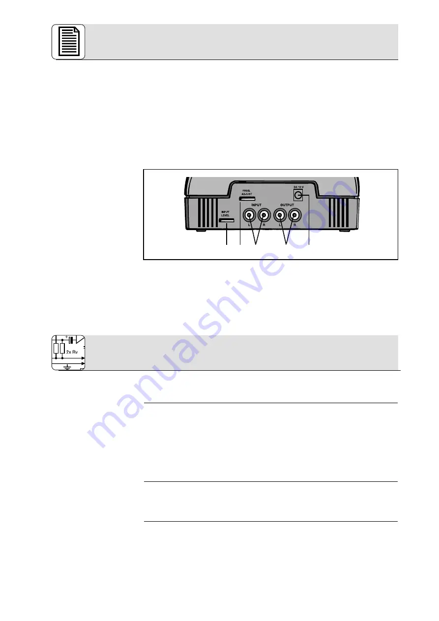
15. INPUT L/R: Left and right RCA audio input jacks.
16. OUTPUT L/R: Left and right RCA audio output jacks.
17. DC 12 V: DC input jack for AC adapter
18. FREQ. ADJUST: frequency tuning control
19. INPUT LEVEL: This rotary control sets the input level to the IVA and Surround
processors as well as the entire audio section. The RF section is modulated auto-
matically by the digital signal transmission circuitry.
20. Charging pins (see fig. 2)
You may connect the transmitter either to a headphones output (mini jack or 1/4” jack),
LINE, or REC outputs.
1.
Before connecting the transmitter to your audio source, switch the audio source OFF.
2.
Referring to fig. 5, plug the red RCA connector (right channel) on the supplied jack
cable into the red INPUT R socket (15) and the white RCA connector (left channel) into
the white INPUT L socket (15) on the transmitter rear panel.
3.
Connect the stereo mini jack plug of the jack cable to the headphones output of your
audio source (refer to fig. 6).
4.
If the headphones output on your equipment is a 1/4” jack, plug the supplied mini jack
to 1/4” adapter jack onto the jack cable. Connect the adapter jack to the headphones
output.
1.
Before connecting the transmitter to your audio source, switch the audio source OFF.
2.
Use the supplied RCA cable to connect the white LINE OUT L or REC OUT L jack on
your audio source to the white INPUT L jack (15) on the transmitter rear panel and the
red LINE OUT R or REC OUT R jack to the red INPUT R jack (15).
By connecting your HEARO 888 TITAN to the ”TAPE” or ”PLAYBACK” inputs on your ampli-
fier, you can enjoy IVA and surround sound through an extra pari of wired headphones in
addition to the wireless ‘phones. Proceed as follows:
1.
Switch your audio source OFF.
2.
Use the supplied RCA cable to connect the white LINE OUT L or REC OUT L jack on
Rear Panel
3.1 Connecting the
Transmitter to
Your Audio Source
3.1.1 Connecting to a
Headphones Output
3.1.2 Connecting to a
LINE or REC Output
3.1.3 Connecting to TAPE
Inputs
3 Audio and Power Connections
19 18 15 16
17
All manuals and user guides at all-guides.com


