11
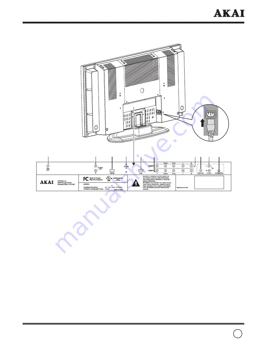
4.2 Rear View
Sketch map
Use the included power cord and connect to an earthed 100-240V, 50/60Hz AC outlet.
Signal input and other terminals:
.
75ΩANT.
: Connect antenna or cable 75 Ohm coaxial Aerial to receive TV/CABLE signal.
.
AUDIO OUTPUT
: Connect audio amplifier or other TV set that with audio input.
.
RS-232
: The D-SUB 9 pins terminal is used as a control port for serial communication
between PC and Panel.
.
PC AUDIO INPUT
: Connect the audio terminal to the audio output terminal of the PC.
.
VGA INPUT
: For PC display purpose. Connects to the Mini D-Sub 15 pins analog
output connector of the PC display card.
.
COMP1(COMPONENT1)YPbPr/YCbCr INPUT
: Connect the separate component
video cables to the device having component video outputs (YPbPr/YCbCr) to the
Y
,
Pb/Cb
, and
Pr/Cr
jacks of the TV.
COMP1(COMPONENT1)YPbPr/YCbCr AUDIO INPUT
: Connect the audio cable to
device’s audio
L
and
R
jacks and to the
L
and
R
audio jacks of the TV.
.
COMP2(COMPONENT2)YPbPr/YCbCr INPUT
: Connect the separate component
video cables to the device having component video outputs (YPbPr/YCbCr) to the
Y
,
Pb/Cb
, and
Pr/Cr
jacks of the TV.
COMP2(COMPONENT2)YPbPr/YCbCr AUDIO INPUT
: Connect the audio cable to
device’s audio
L
and
R
jacks and to the
L
and
R
audio jacks of the TV.
.
VIDEO INPUT
: Connect the component video input terminal to the component output
terminal of the video output device.
.
AUDIO INPUT
: Connect the audio input terminal to the audio output terminal of
the video output device. With S-VIDEO audio input signals share this terminal.
.
S-VIDEO INPUT
: Connects to the S-Video out jack of your VCR or other video
equipment that has S-Video.
LCT2715


