background image

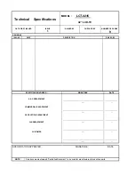
Technical  Specifications 

MODEL :      

LCT-4216 

42” LCD-TV 

DATE FIRST ISSUED 

ISSUE 

RAISED BY 

CHECKED BY 

NUMBER OF PAGES 

REVISIONS 

ISSUED 

DATE 

DESCRIPTION 

RAISED BY : 

SPECIFICATION AGREED : 

SIGNATURE 

DATE 

R & D DEPARTMENT 

......................................................................................

........................... 

...... 

... 

COMMERCIAL DEPARTMENT 

......................................................................................

...... 

........................... 

... 

PRODUCTION DEPARTMENT 

Q/A DEPARTMENT 

......................................................................................

....... 

........................... 

... 

CUSTOMER 

......................................................................................

....... 

........................... 

... 

......................................................................................

....... 

........................... 

... 

SPECIFICATION APPROVED : 

SIGNATURE : 

DATE : 

Only documents stamped “Controlled Document” to be used for manufacture of production parts. 

NOTE : 

Summary of Contents for LCT-4216

Page 1: ...Main IC Specifications Product Specification of POWER board Product Specification of LCD Module Exploded View Spare parts list If you forget your V Chip Password Software Upgrade This manual is the latest at the time of printing and does not include the modification which may be made after the printing by the constant improvement of product ...

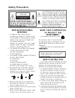
Page 2: ...sk of electric shock to persons The exclamation point within an equilateral triangle is intended to alert the user to the presence of important operating and maintenance servicing instructions in the literature accompanying the appliance CAUTION TO REDUCE THE RISK OF ELECTRIC SHOCK DO NOT REMOVE COVER INSIDE REFER SERVICING TO QUALIFIED CAUTION RISK OF ELECTRIC SHOCK DO NOT OPEN OR BACK NO USER SE...

Page 3: ...let and repeat the AC voltage measurements for each exposed metallic part The measured voltage must not exceed 0 3V RMS This corresponds to 0 5mA AC Any value exceeding this limit constitutes a potential shock hazard and must be corrected immediately The resistance measurement should be done between accessible exposed metal parts and power cord plug prongs with the power switch ON The resistance s...

Page 4: ...OF PAGES 9 REVISIONS ISSUED DATE DESCRIPTION RAISED BY SPECIFICATION AGREED SIGNATURE DATE R D DEPARTMENT COMMERCIAL DEPARTMENT PRODUCTION DEPARTMENT Q A DEPARTMENT CUSTOMER SPECIFICATION APPROVED SIGNATURE DATE Only documents stamped Controlled Document to be used for manufacture of production parts NOTE ...

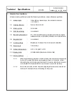
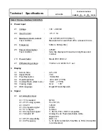
Page 5: ...00 photometer 1 6 Magnetic field no restricted 1 7 Control settings Brightness Contrast Tint Color set at Center 50 1 8 Power input 100 240Vac 1 9 Ambient temperature 20 C 5 C 68 F 9 F 1 10 Display mode 31 5KHz 60Hz Resolution 1366 x 768 1 11 Other conditions 1 11 1 With image sticking protection of LCD module the luminance will descend by time on a same still screen and rapidly go down in 5 minut...

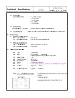
Page 6: ...ing voltage 1 5kVac or 2 2kVdc for 1 sec 3 Display 3 1 Screen Size 42 LCD 3 2 Aspect Ratio 16 9 3 3 Pixel Resolution 1366x768 3 4 Peak Brightness 400 cd m TYPE 3 5 Contrast Ratio Dark room 500 1 TYPE 3 6 Viewing Angle Over 176 3 7 OSD language English Frensh Spanish 4 Signal 4 1 AV Graphic input 4 1 1 TV standard NTSC 4 1 2 TV Tuning system PLL 181Ch 4 1 3 CATV 125CH 4 1 4 Composite signal CVBS 4 ...

Page 7: ... to 85 non condensing 5 2 Storage and Transport 5 2 1 Temperature 20 C to 60 C 4º to 140 F 5 2 2 Relative humidity 5 to 95 6 Panel Characteristics 6 1 Type LG420W02 6 2 Size 42 02inches diagonal 1006mm H x610mm V x59mm D TYPE 6 3 Aspect ratio 16 9 6 4 Viewing angle Over 176 6 5 Resolution 1366X768 6 6 Weight 14 8kg 0 5 kg Net 6 7 Color 16 77 million colors by combination of 8 bits R G B digital 6 ...

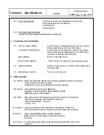
Page 8: ...nals source 7 2 Stand by Button Switch on main power or switch off to enter power Saving modes 7 3 Main Power Switch Turn on or off the unit 8 OSD Function 8 1 Picture State Normal Dark Bright User Display Bright contrast Color Hue Temp warm Cool Normal User Position H posit V posit Phase H size Auto Adjust 8 2 Sound Setup Mode AVC Volume Balance Equalizer 120HZ 500HZ 1 5KHZ 5KHZ 10KHZ BBE Setup G...

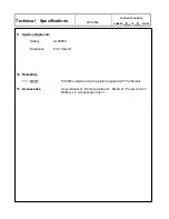
Page 9: ...MBER 6 OF 9 PAGES 9 Agency Approvals Safety UL60950 Emissions FCC class B 10 Reliability 11 1 MTBF 50 000 hours Use moving picture signal at 25 C ambient 11 Accessories User manual x1 Remote control x1 Stand x1 Power cord x1 Battery x 2 Accessories box x 1 ...

Page 10: ...0 24 31 50 31 50 28 32 36 00 40 00 49 50 50 00 57 27 65 00 75 00 78 75 80 37 94 51 108 03 108 04 108 00 1152 x 864 1152 x 864 1 2 3 5 6 7 8 9 10 11 12 13 14 15 16 17 18 19 4 12 Support the Signal Mode A D Sub Mode VGA or DVI NO 480 i 576 i 720p 1280x720 Resolution 576p 720x576 720p 1280x720 480p 720x480 1080i 1920x1080 1080i 1920x1080 Horizontal Frequency KHz Vertical Frequency Hz Dot Clock Freque...

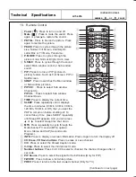
Page 11: ...eatedly until it displays the time in minutes 30 Min 60 Min 90 Min 120 Min 180 Min or Off that you want the PDP to remain on before shutting off To cancel Sleep Time press SLEEP repeatedly until Sleep Off appears And you can press or to select sleep time shut down MTS Press repeatedly to cycle through the Multi channel TV sound MTS options Mono Stereo and SAP Second Audio Program INFO Press to dis...

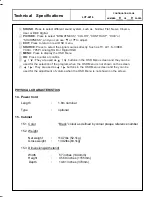
Page 12: ...nu screen and they can be used for the selection of the program when the OSD Menu is not shown on the screen They are used as buttons in the OSD Menu screen and they can be used for the adjustment of volume when the OSD Menu is not shown on the screen CONTINUATION PAGE Technical Specifications LCT 4216 NUMBER 9 OF 9 PAGES PHYSICAL CHARACTERISTICS 14 Power Cord Length 1 8m nominal Type optional 15 ...

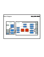
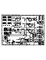
Page 13: ...De Interlacer YCrCb DVI Tuner x 2 SCART1 Sil161B DVI Receiver MSP34x0G Audio Decoder AD9883A ADC VPC3230D Vide Decoder TDA8946 Audio AMP S Video YPbPr Video2 Speaker M52790 A V Switch uPD64083 3D Y C Separator SDA5550 TVText Pro Z86229 V Chip CC VPC3230D Video Decoder Main Board W78E65B System Control Z86229 V Chip CC Sub Board ...

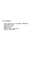
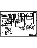
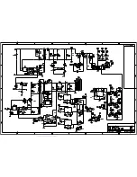
Page 14: ...Circuit Diagram Power supply board of LCD Module PSM250 405 Main Video board Audio Tuner board Keypad board Remote control receiver board Remote control board ...

Page 15: ...CN A B VCC B 3 5VSB 5 AC VC B ON OFF AC AC AC VC CN B 5V 12V ...

Page 16: ...B A VCC 5 3 12V 24V C B A 5V 12V 24V 5V 1 REF CN A C 12V 24V 5VSB 5V B ZD5 R93 B CN B 5VSB VC 12V Q14 VC ON OFF 12V VC PC5 2 ...

Page 17: ...DbhM4812V12_Vtek_BOM sch 1 Wed Oct 06 23 58 07 2004 ...

Page 18: ...DbhM4812V12_Vtek_BOM sch 2 Wed Oct 06 23 58 08 2004 ...

Page 19: ...DbhM4812V12_Vtek_BOM sch 3 Wed Oct 06 23 58 10 2004 ...

Page 20: ...DbhM4812V12_Vtek_BOM sch 4 Wed Oct 06 23 58 11 2004 ...

Page 21: ...DbhM4812V12_Vtek_BOM sch 5 Wed Oct 06 23 58 15 2004 ...

Page 22: ...DbhM4812V12_Vtek_BOM sch 6 Wed Oct 06 23 58 16 2004 ...

Page 23: ...DbhM4812V12_Vtek_BOM sch 7 Wed Oct 06 23 58 18 2004 ...

Page 24: ...DbhM4812V12_Vtek_BOM sch 8 Wed Oct 06 23 58 29 2004 ...

Page 25: ...DbhM4812V12_Vtek_BOM sch 9 Wed Oct 06 23 58 20 2004 ...

Page 26: ...DbhM4812V12_Vtek_BOM sch 10 Wed Oct 06 23 58 22 2004 ...

Page 27: ...DbhM4812V12_Vtek_BOM sch 11 Wed Oct 06 23 58 32 2004 ...

Page 28: ...DbhM4812V12_Vtek_BOM sch 12 Wed Oct 06 23 58 25 2004 ...

Page 29: ...DbhM4812V12_Vtek_BOM sch 13 Wed Oct 06 23 58 27 2004 ...

Page 30: ...Dbh1S4909V12 sch 1 Thu Oct 07 00 30 41 2004 ...

Page 31: ...Dbh1S4909V12 sch 2 Thu Oct 07 00 30 42 2004 ...

Page 32: ...Dbh1S4909V12 sch 3 Thu Oct 07 00 30 43 2004 ...

Page 33: ...Dbh1S4909V12 sch 4 Thu Oct 07 00 30 45 2004 ...

Page 34: ...Dbh1S4909V12 sch 5 Thu Oct 07 00 30 47 2004 ...

Page 35: ...Dbh1S4909V12 sch 6 Thu Oct 07 00 30 49 2004 ...

Page 36: ...Dbh1S4909V12 sch 7 Thu Oct 07 00 30 50 2004 ...

Page 37: ...DUBHE OSD Ver1 1_NAKS sch 1 Mon Oct 18 11 47 11 2004 ...

Page 38: ...0025 TTX sch 1 Thu May 05 23 47 54 2005 ...

Page 39: ... 3 pcs PCB including 2 pcs INVERTER board L R 1 pc T CONTROL board 2 SIGNAL PROCESS There are 7 pcs PCBs including 1 pc Tuner board 1 pc Audio board 1 pc Main digital board 1 pc Keypad board 1 pc Remote Control Receiver board 2 pc L R Speakers converter board 3 POWER There are 1 pc PCB for power ...

Page 40: ......

Page 41: ...nverter the Digital to fit the panel display mode and output the LVDS signal to Panel 3 Tuner Board Convert TV RF signal to video and audio signal to Main board 4 Audio board 1 Decoder the TV SIF signal to audio signal 2 Converter the audio to audio Ampifile and out put to the external speaker 3 3D comb filter 5 KEYBOARD To get the main button control on LCD_TV as SOURCE MENU CHANEL CHANEL VOL VOL...

Page 42: ... from Key Switch or Remote Receiver 2 When the ON signal from Key Switch or Remote Receiver is detected Micro Processor will send ON Control signals to Power Then Power sends 5Vsc 18Vsc 24V and RLY ON Vs ON to PCBs working This time VIF will send signals to display back light OSD on the panel and start to search available signal sources If the audio signals input them will be amplified by Audio AM...

Page 43: ...r light will pass through the energized display but will be blocked by the rear polarizer An LCD in this form is acting as a light shutter Displays with variable characters are created by selectively etching away the conductive surface that was originally deposited on the glass Etched areas become the display s background unetched areas become the display s characters Diagram 3A The off state of a...

Page 44: ... Video Signal Processor uPD64083 Three Dimensional Y C Separation LSI With On Chip Memory AD9883A 110MSPS 140MSPS Analog Interface VPC 323XD Comb filter Video Processor Si161B Panel Link Receiver Z86229 NTSC Line 21 CCD decorder MSP34x0G Multistandard Sound Processor ...

Page 45: ...uffer including motion adaptive temporal deinterlacing with film mode detection When used in combination with the new third generation scaler this advanced video processing technology delivers the highest quality video for advanced displays Both input ports support integrated DVI 1 0 content protection using standard DVI receivers A new advanced OSD Generator with more colors and larger sizes supp...

Page 46: ... The AD9883A is a complete 8 bit 140 MSPS monolithic analog interface optimized for capturing RGB graphics signals from personal computers and workstations Its 140 MSPS encode rate capability and full power analog bandwidth of 300 MHz supports resolutions up to SXGA 1280 1024 at 75 Hz The AD9883A includes a 140 MHz triple ADC with internal 1 25 V reference a PLL and programmable gain offset and cl...

Page 47: ...s This high level of integration enables simple flexible cost effective solutions that require fewer components Features Built In Memory Controller Motion Adaptive Deinterlace Processor Intelligent Edge Deinterlacing Digital Color Luminance Transient Improvement DCTI DLTI Interlaced Video Input Options including NTSC and PAL Independent horizontal and vertical scaling Copy Protection Two Wire Seri...

Page 48: ...cludes the Wide Clear Vision ID signal Japanese local format decoder and ID 1 signal decoder FEATURES On chip 4 Mbit frame delay memory 4 Operation mode Compatible to the µPD64082 Motion adaptive 3D Y C separation for Composite video input Frame recursive Y C NR for Y C separated video input Frame comb type YNR 1H delayed C signal for Y C separated video input 2D Y C separation Frame recursive Y C...

Page 49: ... 656 output interface peaking contrast brightness color saturation and tint for RGB YCrCb and CVBS S VHS high quality soft mixer controlled by Fast Blank PIP processing for four picture sizes or of normal size with 8 bit resolution 15 predefined PIP display configurations and expert mode fully programmable control interface for external field memory I2 C bus interface one 20 25 MHz crystal few ext...

Page 50: ...ology simplifies PC and display interface design by resolving many of the system level issues associated with high speed mixed signal design providing the system designer with a digital interface solution that is quicker to market and lower in cost Low Power Operation 280mA max current consumption at 3 3V core operation Time staggered data output for reduced ground bounce and lower EMI Sync Detect...

Page 51: ... application The robust nature of the Z86229 helps the device conform to the transmissionformat defined in the Television Decoder Circuits Act of 1990 and in accordance with the Electronics Industry Association specification 608 EIA 608 The Line 21datastreamcanconsistof datafrom severaldata channels multiplexed together Field 1 consists of four data channels two Captions and two Texts Field 2 cons...

Page 52: ...n for BTSC and EIA J The MSP 34x0G has optimum stereo perfor mance without any adjustments All MSP 34xxG versions are pin compatible to the MSP 34xxD Only minor modifications are necessary to adapt a MSP 34xxD controlling software to the MSP 34xxG The MSP 34x0G further simplifies con trolling software Standard selection requires a single I2 C transmission only The MSP 34x0G has built in automatic ...

Page 53: ...MODEL NO PSM250 405 SPECIFICATION REVISION 01 DATE 2005 03 14 REV 01 PAGE 3 1 REVISION HISTORY Date Rev Page Summary 2005 03 14 00 All 2005 03 15 01 6 Change 24V peak power 8A 3 minutes ...

Page 54: ...en Power savor function 3 ELECTRICAL SPECIFICATIONS 3 1 AC INPUT CHARACTERISTICS 3 1 1 Input voltage For the outputs to be within their specified limits the input voltage shall be single phase sinusoidal with the RMS input voltage within the following limits Minimum Nominal Maximum Unit 90 120 240 264 VRMS Note The input voltage should be remained within limit 1V 3 1 2 Input frequency Minimum Nomi...

Page 55: ... 25 ambient cold starting condition Less than 100A at 240Vac and 25 ambient cold starting condition 3 1 5 Efficiency 80 or greater at DC output with full loading and nominal AC input voltage range of 120V 240Vac 60Hz 50Hz 3 1 6 Power factor Power factor of power supply shall meet 0 90 minimum full load to be meet EN61000 3 2 3 1 7 Power Line Harmonics requirement PF The input current harmonics req...

Page 56: ...e shall stay within regulation band as specified in above for a 25 step load change at 1A uSec Load capacitance is defined at minimum load capacitance shall be zero and maximum load capacitance shall be 2200uF for 35V output Note 3 Ripple is defined as a composite of a power line frequency component plus a high frequency component due to the power oscillator Common mode noise which may be observed...

Page 57: ... enable circuit shall be SELV compliant 3 2 3 Over shoot Any over shoot at initial turn on and turn off must be less than 10 of nominal voltage value 3 2 4 Turn on delay time 2 sec Max 120Vac 60Hz 3 2 5 Rise time The output voltage should be rise from 0 volt and settle within regulation in less than 30 ms measured at T1 firm apply of nominal AC input voltage Maximum Unit 30 ms 3 2 6 Hold up time 5...

Page 58: ... shall be protected from over voltage fault at all conditions including open loop by breakdown that is set to trip as following table 4 3 Short circuit protection The output will withstand a short circuit across the outputs with latch off function Output can be shorted without damage Item CH1 CH2 CH3 CH4 Output Voltage 5V 5Vsb 18V 24V Over voltage protection 6 5 7 Auto restart 22 25 3 27 6 31 2 Ov...

Page 59: ...non condensing Condition Minimum Maximum Unit Operating 20 90 RH Storage 5 95 RH 5 3 Altitude Operating From sea level to 10 000 ft with 40 maximum ambient temperature Storage From sea level to 40 000 ft 5 4 Vibration and shock The PSU shall withstand forces of 2 G at variable recurrent frequencies of 10 to 55 Hz and a simulated transportation test The transportation test will consist of a 1 2 G v...

Page 60: ...MS Test item Test specification IEC Standard ESD Contact 8 KV 61000 4 2 ESD Air 15 KV Contact 8KV 61000 4 2 RS FR 26 MHz 1 GHz Field Strength 3 V M 61000 4 3 EFT 2 KV on AC power line 61000 4 4 SURGE 1 KV L N 2 KV L N PE 1 2 50Usec 61000 4 5 CS 3 V M 61000 4 6 DIPS 0 250 Cy 40 5 Cy 70 5 Cy 61000 4 11 6 3 Conducted EMI For 240 Vac input operation the PSU must below the limit of CISPR 22 Class B for...

Page 61: ...ielectric with stand Hi Pot Test 6 5 1 Primary to Secondary 3000 Vac or 4242 Vdc Hi Pot Test from primary to secondary for a minimum of one second trip current 10mA 6 5 2 Primary to FG 1500 Vac Hi Pot Test from primary to FG for a minimum of one second 6 6 Insulation resistance 6 6 1 Aafter 500Vdc is applied which between primary to secondary or secondary to FG for one minute the Impedance shall b...

Page 62: ... shall not exceed 45 7 3 Surge withstand and EFT The PSU shall withstand the line transient for both Common Mode at 2 KV and Differential Mode at 2 KV operations 7 4 Burn in 100 burn in on production line with 80 100 loading at 40 5 environment temperature for 4 hours 8 ACOUSTICS The noise should be less than 40 dB when one meter away from the PSU at full loading 9 MECHANICALS 9 1 Input connection...

Page 63: ...MODEL NO PSM250 405 SPECIFICATION REVISION 01 DATE 2005 03 14 REV 01 PAGE 13 ...

Page 64: ...MODEL NO PSM250 405 SPECIFICATION REVISION 01 DATE 2005 03 14 REV 01 PAGE 14 ...

Page 65: ...ness super wide viewing angle high color gamut high color depth and fast response time are important CN1 30pin LVDS 5pair Select Source Driver Circuit TFT LCD Panel 1366 RGB 768 pixels G1 S1 S1366 G768 Back light Assembly 20CCFL 10CNs High RGB Timing Controller LVDS Rx integrated Gate Driver Circuit 10CNs High Inverter CN2 CN3 24 0V 2X GND 2X SDRAM EEPROM LUT Power Circuit Block SDA SCL MEM CTRL R...

Page 66: ...nverter LCD circuit Unit RH 90 10 HOP Operating Ambient Humidity RH 90 10 HST Storage Humidity C 50 20 TST Storage Temperature VDC 5 25 0 30 VOFF VON Inverter Control Voltage at 25 2 C VDC 14 0 0 3 VLCD Power Input Voltage Max Min Parameter Remark Value Symbol Note 1 Temperature and relative humidity range are shown in the figure below Wet bulb temperature should be 39 C Max and no condensation of...

Page 67: ... Power Consumption 3 A 3 0 IRUSH Rush current VDC 12 6 12 0 11 4 VLCD Power Input Voltage 2 mA 835 700 ILCD Power Input Current Circuit Parameter Symbol Max Typ Min Note Unit Value Note 1 The specified current and power consumption are under the VLCD 12 0V 25 2 C fV 60Hz condition whereas mosaic pattern 8 x 6 is displayed and fV is the frame frequency 2 The current is specified at the maximum curr...

Page 68: ...es Notes 1 Electrical characteristics are determined after the unit has been ON and stable for approximately 120 minutes at 25 2 C The specified current and power consumption are under the typical supply Input voltage 24V and Vbr 3 3V it is total power consumption The ripple voltage of the power supply input voltage is under 0 2 Vp p LPL recommend Input Voltage is 24 0V 5 2 Brightness Control This...

Page 69: ...xternal VBR input from System to LCD module VBR_EXT 28 Ground GND 29 2 Ground GND 30 Power Supply 12 0V VLCD 2 Power Supply 12 0V VLCD 3 Power Supply 12 0V VLCD 4 Ground GND 5 Ground GND 6 Ground GND 7 Ground GND 8 1 Select LVDS Data format Select 9 AI Enable H Enable L Disable Enable 10 LVDS Receiver Signal RB 16 Ground GND 17 LVDS Receiver Signal RC 18 LVDS Receiver Signal RC 19 Ground GND 20 Gr...

Page 70: ...KOUT TxCLKOUT TxOUT3 TxOUT3 51 52 54 55 56 3 50 2 4 6 7 11 12 14 8 10 15 19 20 22 23 24 16 18 27 28 30 31 DS90C385 or Compatible 5 6 8 9 11 12 14 15 17 18 9 30 RxIN0 RxIN0 RxIN1 RxIN1 RxIN2 RxIN2 RxCLKIN RxCLKIN RxIN3 RxIN3 LG DISM LCD Test 100Ω 100Ω 100Ω 100Ω 100Ω 48 47 46 45 42 41 40 39 38 37 FI X30SSL HF Timing Controller GND GND LCD Module Note 1 The LCD Module uses a 100 Ohm Ω resistor betwee...

Page 71: ...T TxCLKOUT TxOUT3 TxOUT3 DS90C385 or Compatible 5 6 8 9 11 12 14 15 17 18 9 30 RxIN0 RxIN0 RxIN1 RxIN1 RxIN2 RxIN2 RxCLKIN RxCLKIN RxIN3 RxIN3 LG DISM LCD Test 100Ω 100Ω 100Ω 100Ω 100Ω 48 47 46 45 42 41 40 39 38 37 FI X30SSL HF Timing Controller 50 2 51 52 54 55 56 3 8 10 4 6 7 11 12 14 16 18 15 19 20 22 23 24 27 28 30 31 Vcc GND LCD Module Note 1 The LCD module uses a 100 Ohm Ω resistor between p...

Page 72: ...OWER GND GND 7 POWER GND GND 8 Note 1 0V 3 3V VBR 11 POWER GND GND 10 POWER GND GND 9 POWER GND GND 6 Power Supply 24V VBL 5 Power Supply 24V VBL 4 Power Supply 24V VBL 3 Power Supply 24V VBL 2 Power Supply 24V VBL 1 0V 5 0V On Off 12 Remarks Description Symbol Pin No Notes 1 GND is connected to the LCD module metal frame PCB 1 2 3 12 11 10 S12B PH SM3 TB JST Japan Solderless Terminal Co Ltd 2 0V ...

Page 73: ...ent 50cm FIG 1 Optical Characteristic Measurement Equipment and Method Ta 25 2 C VLCD 12 0V fV 60Hz Dclk 72MHz VBR 3 3V Table 12 OPTICAL CHARACTERISTICS With AI 1 000 700 CR with AI 6 Without AI Gray Scale 5P y axis down φ 270 y axis up φ 90 x axis left φ 180 x axis right φ 0 88 85 θd 88 85 θu 88 85 θl 5 degree 88 85 θr Viewing Angle CR 10 WHITE BLUE GREEN RED 0 610 Gy 0 282 Gx 0 073 By 0 147 Bx 0...

Page 74: ...nance variation H A V B A H 4 mm B V 4 mm H 930 25 mm V 523 01 mm H V Active Area FIG 2 Measure Point for Luminance Response time is defined as the following figure and shall be measured by switching the input signal for Gray N and Gray M Gray M Gray N TrR TrD 100 90 10 0 Optical Response N M 0 Black 255 White N M Gray N FIG 3 Response Time ...

Page 75: ...Product Specification 2 LC420W02 Liquid Crystal Display Ver 1 1 August 12 2004 Dimension of viewing angle range Normal Y E φ θ φ 0 Right φ 180 Left φ 270 Down φ 90 Up FIG 4 Viewing Angle ...

Page 76: ...g of the LCD module 1006 0 mm Horizontal Outline Dimension 523 01 mm Vertical Hard coating 3H Anti glare treatment of the front polarizer Surface Treatment 11 800g Typ 12 400g Max Weight 531 0 mm Vertical 610 0 mm Vertical 59 0 mm Depth 930 25 mm Horizontal Active Display Area 939 0 mm Horizontal Bezel Area Value Item Table 14 MECHANICAL CHARACTERISTICS Note 1 Please refer to a mechanic drawing in...

Page 77: ...Product Specification 2 LC420W02 Liquid Crystal Display Ver 1 1 August 12 2004 FRONT VIEW ...

Page 78: ...Product Specification 2 LC420W02 Liquid Crystal Display Ver 1 1 August 12 2004 REAR VIEW ...

Page 79: ... wave 2ms Direction X Y Z One time each direction Shock test non operating 6 Wave form random Vibration level 1 0Grms Bandwidth 10 500Hz Duration X Y Z 10 min One time each direction Vibration test non operating 5 Ta 0 C 240h Low temperature operation test 4 Ta 40 C 50 RH 240h High temperature operation test 3 Ta 20 C 240h Low temperature storage test 2 Ta 50 C 240h High temperature storage test 1...

Page 80: ...oaks with petroleum benzine Normal hexane is recommended for cleaning the adhesives used to attach front rear polarizers Do not use acetone toluene and alcohol because they cause chemical damage to the polarizer 8 Wipe off saliva or water drops as soon as possible Their long time contact with polarizer causes deformations and color fading 9 Do not open the case because inside circuits do not have ...

Page 81: ... surface should not come in contact with any other object It is recommended that they be stored in the container in which they were shipped 9 6 Handling Precautions for Protection Film 1 The protection film is attached to the bezel with a small masking tape When the protection film is peeled off static electricity is generated between the film and polarizer This should be peeled off slowly and car...

Page 82: ... LCD Module Handling Guide Handling Guide Handling Guide Color TFT LCD Module is apt to be damaged by both electrical and mechanical stresses Users therefore are requested to follow the Guidance of handling color TFT LCD Module on the followings System Assembler System Assembler End Customer ...

Page 83: ...3 4 Keep LCD dust free LCD Module is sensitive against dust Dust can cause functional and or visual defect So please keep LCD dust free Prevent overheat High temperature on the surface of the screen may cause poor quality Please make LCD used on specified temperature Heat from backlight should be considered 5 Need EMI solution LCD Module is produced to be EMI solved However system is needed to be ...

Page 84: ...e LCD Physical stress can cause the defect such as broken Certainly connect the I F B L connectors Incomplete connection with LCD can cause burnt in Backlight connector or damage the interface IC Taping after connecting is highly recommended 11 12 Do not operate for a long time under the same pattern Operating LCD for a long time under the same pattern can cause image persistence and can damage it...

Page 85: ... backlight wire front side of LCD the backlight connector can hurt the surface of polarizer Do not provide strong pressure at connecting Strong pressure can transfer the force to TCP which is the weakest parts of LCD Eventually can make TCP crack or other unexpected defect 17 18 Never connect disconnect at power on LCD consists of CMOS which is known as weak component against EOS Please do not con...

Page 86: ...er surface with materials over HB hardness 3 4 Keep out of water Water on in the LCD can cause electrical short or corrosion Please wipe out or dry water carefully Prevent swift Temperature Humidity change Swift temperature and or humidity change can make dew condensation or ice which cause nonconformance such as malfunction 5 6 LCD is not proper to be used at high temperature and high humidity Pl...

Page 87: ...42LCD PCS 1 16 E6203 042001 DISPLAY LCD LG42 WXGA TFT LCD LC42W PCS 1 17 E7301 011002 BATTERY AA R6P1 5V 2 PCS 2 18 E7802 002001 PCB ASSY MAIN BOARD EROOM FOR 42LCD PCS 1 19 E7802 002002 PCB ASSY TUNER BOARD FOR 42LCD EROOM PCS 1 20 E7802 002003 PCB ASSY POWER FOR 42LCD EROOM PCS 1 21 774PL42OB01 01 POWER INPUT ASSY PCS 1 22 771 L42OB02 01 OUTSIDE SPEAKER CONNECTOR ASSY PCS 1 23 771 L42OB01 03 REM...

Page 88: ... 30 436 L42OB01 01S TERMINAL SHEET PCS 1 31 457 42D101 01 CLAMP ID 4 3MM L 46MM PCS 10 32 481 L42OB01 01S POWER SHIELD BOX BOTTOM PCS 1 33 483 L42AA13 01S SHIELD COVER FOR PANEL PCS 1 34 483 L42OB01 01 MAIN PCB SHIELD BOX COVER PCS 1 35 483 L42OB02 01 POWER BOX COVER PCS 1 36 484 P46T11 01 SPACER SLEEVE H 11 8MM PCS 1 37 489 L42AA01 01 DECORATION BAR PCS 2 38 489 P46T04 01 DECORATION COVER FOR SCR...

Page 89: ...02 005005 21 DOUBLE SIDE TAPE NITTO NO 500 5MMX5 RLS 0 0448 69 844 L42OB01 01 WOODEN PALLET 1445X1115 PCS 0 33 四 PACKING 1 300 L42OB01 01N POLYFOAM EPE BOTTOM L PCS 1 2 300 L42OB02 01N POLYFOAM EPE BOTTOM R PCS 1 3 300 L42OB03 01N POLYFOAM EPE TOP L PCS 1 4 300 L42OB04 01N POLYFOAM EPE TOP R PCS 1 5 300 L42OB05 01N POLYFOAM EPE BOTTOM MID PCS 1 6 300 L42OB06 01N POLYFOAM EPE TOP MID PCS 1 7 310 04...

Page 90: ......

Page 91: ...nect the RS 232C input jack to an external control device such as a computer and software upgrade Type of connector D Sub 9 pin male 1 No Pin name 5 1 No connection 2 RXD Receive data 3 TXD Transmit data 4 DTR DTE side ready 5 GND 9 6 DSR DCE side ready 7 RTS Ready to send 6 8 CTS Clear to send 9 No Connection RS 232C configurations 7 wire configuration 3 wire configuration Standard RS 232C cable ...

Page 92: ...uter Open the software Flash Upgrader exe Point Flash on the interface of the Flash Upgrader exe Press STANDBY button on the front panel or POWER button of Remote control Power indicator green the LCD TV is in power ON mode software start upgrader immediately Waiting for the upgrader programing when it is finished the LCD TV will auto power on After the upgrader is finished shut down the power swi...

Reviews: