DISASSEMBLY INSTRUCTIONS
B2-3
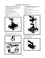
Fig. 2-8-A
Fig. 2-8-B
2-8: CLAMPER ASS'Y/DISC GUIDE ARM/DISC R
LEVER (Refer to Fig. 2-8-A)
Unlock the support (1) and remove the Clamper Ass'y.
Unlock the support (2) and remove the Disc Guide Arm.
Unlock the support (3) and remove the Disc R Lever.
1.
2.
3.
Clamper Ass'y
(1)
(3)
(2)
Disc Guide Arm
Disc R Lever
NOTE
1. When installing the Clamper Ass'y, check if the Clamper
Ass'y is locked correctly as Fig. 2-8-B.


