29CTF05BS
3 – 29
PAL CHROMA ADJUSTMENT
I
D
N
O
C
T
N
E
M
T
S
U
J
D
A
T
N
I
O
P
T
N
E
M
T
S
U
J
D
A
O
N
S
K
R
A
M
E
R
R
O
M
R
O
F
E
V
A
W
E
R
U
D
E
C
O
R
P
/
N
O
I
T
1
SUB COLOUR
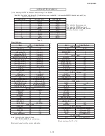
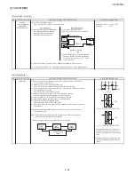
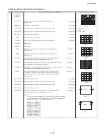
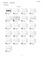
1. Receive the "PAL Color Bar" signal.
(I2C BUS CONTROL) 2. Make the image normal with the remote controller.
3. Connect the oscilloscope to TP47R (IC851 #9). ( Use Probe 10:1)
Range : 2V / Div
Sweep time: 20m sec / Div
4. Set the sub color adjustment mode with the remote controller, and vary the sub
color data to make 100% W of the color bar and RED at the same level for
adjustment shown in Fig 1-1.
NTSC CHROMA ADJUSTMENT
I
D
N
O
C
T
N
E
M
T
S
U
J
D
A
T
N
I
O
P
T
N
E
M
T
S
U
J
D
A
O
N
S
K
R
A
M
E
R
R
O
M
R
O
F
E
V
A
W
E
R
U
D
E
C
O
R
P
/
N
O
I
T
1
SUB-TINT
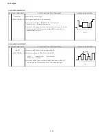
(1) Receive the "NTSC 3.58 Colour Bar" signal through AV IN.
(I2C BUS CONTROL) (2) Connect the oscilloscope to TP47B (P860 Pin4) BLUE-OUT
Range
: 100mV/Div (AC)
(Use Probe 10:1)
Sweep time
: 10sec/Div
(3) Select the "SUB-TINT" item in the ADJUSTMENT MODE. Adjust the "SUB-TINT"
data to obtain the waveform shown as Fig 1-1 (W and Mg same level).
Cy
G
B
75% W Y 100% W Mg
R
Fig 1-1
Same Level
W
Y
Cy
G
Mg
R
B
Fig 1-1
Summary of Contents for 29CTF05BS
Page 1: ...Service manual Colour TV set 29CTF05BS ...
Page 46: ...29CTF05BS 7 2 ...
Page 50: ...29CTF05BS 10 2 ...
Page 51: ...29CTF05BS 10 3 2 SCHEMATIC DIAGRAM CRT UNIT 29CTF05BS ...
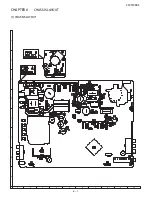
Page 53: ...29CTF05BS 11 2 2 PWB A MAIN UNIT 1 MAIN UNIT COMPONENT SIDE ...
Page 54: ...29CTF05BS 11 3 ...
Page 55: ...29CTF05BS 11 4 2 MAIN UNIT CHIP PARTS SIDE ...
Page 56: ...29CTF05BS 11 5 ...

