29CTF05BS
3 – 25
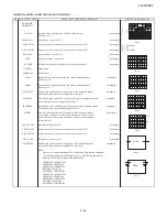
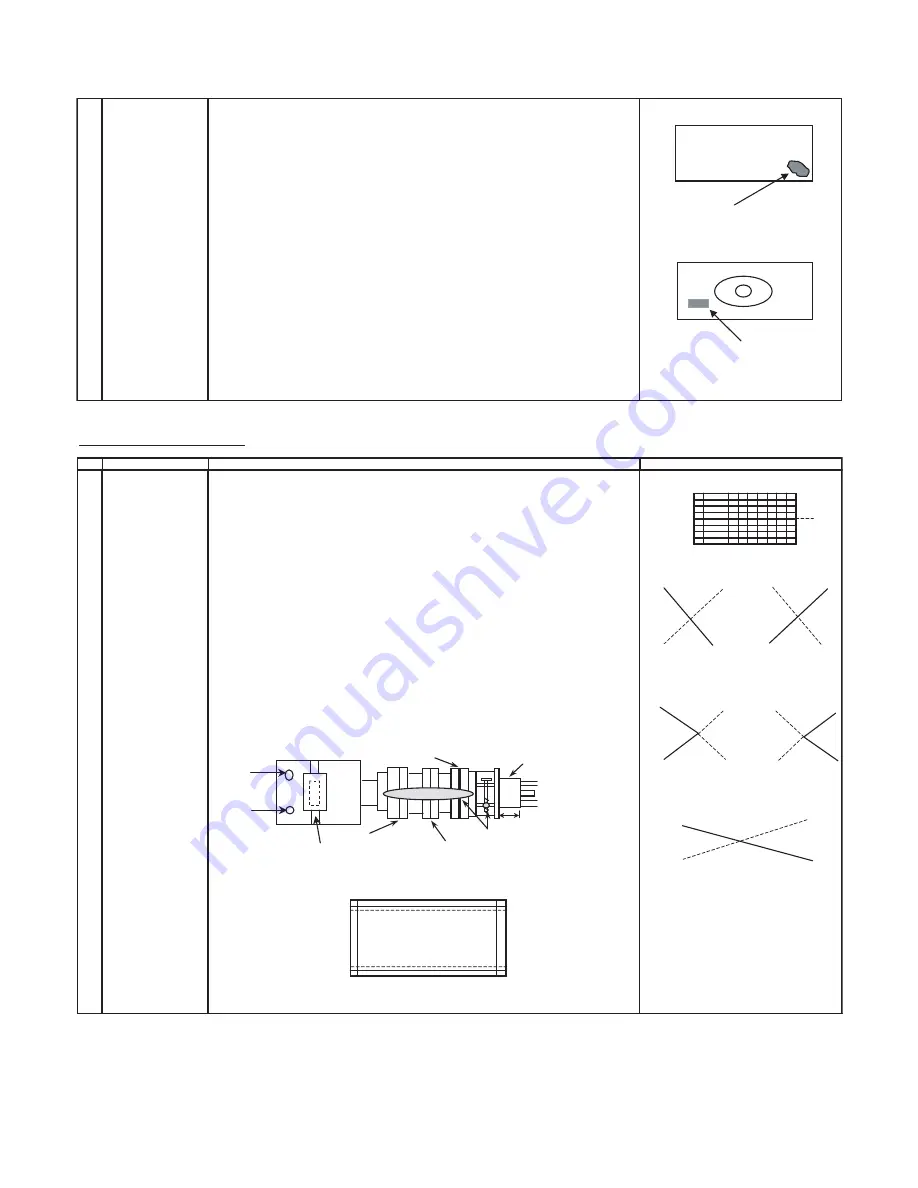
(CRT surface)
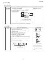
Mislanding
(CRT back)
compensation magnet
Fig-1
2
UNIFORMITY
Before adjustment begin,Horizontal magnetic field = 0G
ADJUSTMENT
Vertical magnetic field = Each destination's adjustment magnetic field
(To perform after the
Make sure to degauss it.
purity and
convergence
(North direction red uniformity)
adjustment)
(1) Horizontal mf = Set to monocolor screen red and adjust to +0.25G.
(2) Pay attention to the edge of CRT, if the landing is poor adjust by attaching the compensation
magnet at the back of CRT.
(refer to Fig-1)
(South direction red uniformity)
(1) Horizontal mf = Set to monocolor screen red and adjust to -0.25G.
(2) Pay attention to the edge of CRT, if the landing is poor adjust by attaching the compensation
magnet at the back of CRT.
(The same method is applied for adjustment of monocolor screen blue for blue uniformity, and
changing both the magnetic field for north and south direction.)
*During the pasting of compensation magnet, use the crosshatch pattern.
Make sure there is no blur or bendlines occur.
If the blur or bend are serious, adjust the location of compensation magnet to make it better.
CONVERGENCE ADJUSTMENT
NO ADJUSTMENT POINT
1
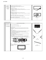
CONVERGENCE ADJ (1) Receive the " Crosshatch Pattern" signal.
(To be done after the
(2) Using the remote controller, call NORMAL mode.
purity adjustment.)
( Static convergence )
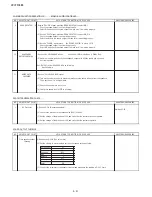
1. Overlap blue and red with the open-/closing angle and rotation of the 4 pole magnet.
2. Overlap green on blue and red with the open-/closing angle and rotation of the 6 pole
magnet.
( Dynamic convergence )
1. Fix the wedges in a position so that the deflection york neck is at the center of top bottom
and left right. (Straight line and without any blur horizontal / vertical line).
2. Adjust the Red, Blue, upper and lower of the centre y axis on the screen by using the
Volume (VR2, VR1) at the deflection york.
(Refer to Fig-1 and Fig-2)
3. If the Horizontal Red, Blue (XV) on the screen centre X axisis shifted, correct the Red, Blue
(XV) by adjusting the balance coil on the deflection york.
(Refer to Fig-3)
4. After confirm that there is no problems on the entire screen, bond each wedge on CRT
and glass tape on it. Fastening the screws of DY and magnet unit (purity, 4 - pole and
6 pole), then coat the lacquer paint on DY fastening screw and magnet unit fastening screw.
Note:
In case of poor convergence adjustment on the top and bottom and of the screen, adjust DY by
swing rightward and leftward.
(Refer to Fig-4)
Fig-4
Adjust by Swing DY
ADJUSTMENT CONDITION / PROCEDURE
WAVEFORM OR REMARKS
VR1
VR2
Balance Coil
Lacquer
Purity Magnet
4-Pole Magnet
6-Pole Magnet
25mm ± 0.5mm
CRT NECK
X axis
Y axis
B
R
R
B
Fig-1
Adjust by VR1
B
R
R
B
Fig-2
Adjust by VR2
B
R
Fig-3
Adjust by Balance Coil
Summary of Contents for 29CTF05BS
Page 1: ...Service manual Colour TV set 29CTF05BS ...
Page 46: ...29CTF05BS 7 2 ...
Page 50: ...29CTF05BS 10 2 ...
Page 51: ...29CTF05BS 10 3 2 SCHEMATIC DIAGRAM CRT UNIT 29CTF05BS ...
Page 53: ...29CTF05BS 11 2 2 PWB A MAIN UNIT 1 MAIN UNIT COMPONENT SIDE ...
Page 54: ...29CTF05BS 11 3 ...
Page 55: ...29CTF05BS 11 4 2 MAIN UNIT CHIP PARTS SIDE ...
Page 56: ...29CTF05BS 11 5 ...

