Version 3.11 Addendum
Page 4
It is essential that the AKAINET TERMINATOR switch is switched to the ON position on
the first and last units in the chain. Failure to do so will prevent correct communications
and the system will not work correctly.
NOTE: The AKNET interface used in the Akai DR16pro system is 10-Base-2
Ethernet. There are certain rules that must be adhered to when setting up the system
to ensure reliable operation:
• All cables should be 50 ohm impedance.
• There should be a maximum of 185m of cable in the system between the first and
last nodes.
• There should be at least 0.5m of cable between each connection.
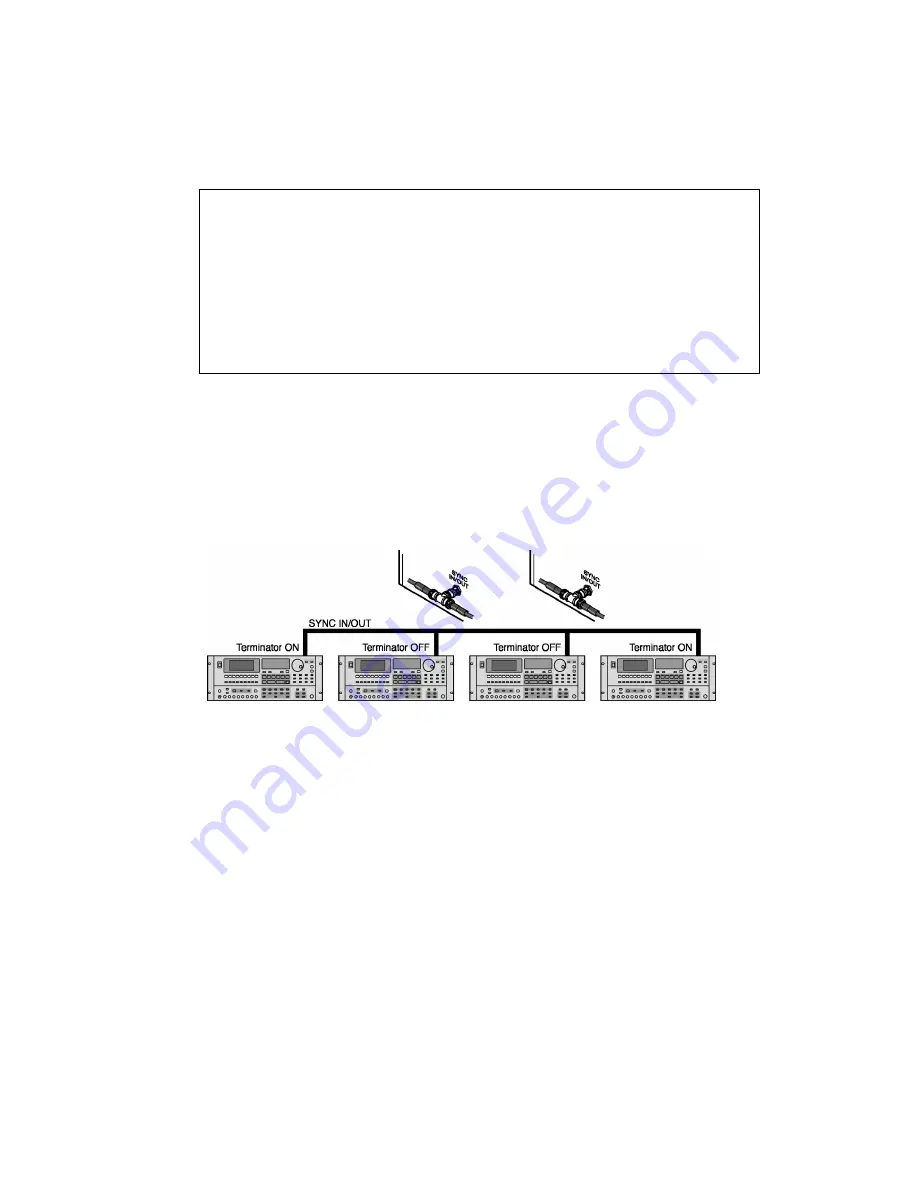
Sync Connections
The SYNC IN/OUT connectors on each DR16pro should be connected together to allow the
internal sample clocks of each machine in the system to be synchronised. This should be
done using standard video BNC cables. These are chained between the SYNC IN/OUT
BNC connectors on each DR16pro using BNC ‘T’ connectors to link each cable where
necessary.
It is essential that the SYNC IN/OUT TERMINATOR switch is switched to the ON position
on the first and last units in the chain. Failure to do so will prevent the system from
synchronising correctly.


