Page 9
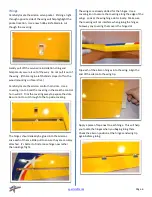
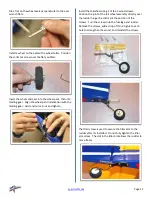
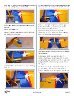
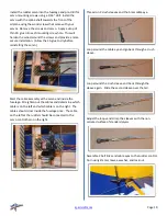
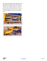
Attach the servo wire to the installation string and gently
pull the wire through the wing as you insert the servo
into the wing.
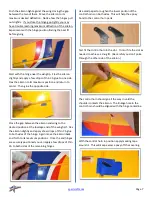
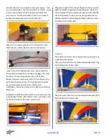
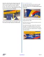
Insert the servo into the pocket with the drive spline
towards the front of the wing. Pre-drill for the servo
mounting screws using a 1/16” drill.
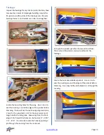
Remove the servo
and apply a drop of thin CA glue into each mounting
screw hole. This will harden the wood around the screws
and provide a more secure installation. Allow the CA glue
to dry before reinstalling the servo.
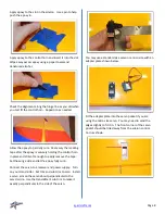
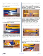
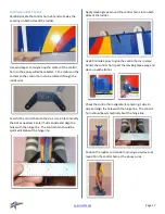
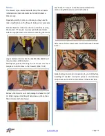
Assemble a ball link to each end of a connecting rod.
Use a socket head screw, a flat washer and a nylon lock
nut to connect a ball link to the servo control horn. (The
brass ball in the link is offset. The larger reveal side
should be against the control horn and servo arm shown
below.)
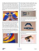
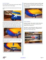
Check the length of the assembly to the servo arm with
the aileron level with the wing. When the correct length
of the assembly is found, connect the ball link to the
servo arm. (Always adjust the connecting rod length with
the servo powered up and centered.)
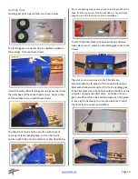
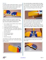
Carefully locate the mounting holes in the side force
generators and trim away the covering. The wing tips
have a blind nut installed beneath the covering. Use a
hobby knife to trim away the covering. (Use the holes in
a spacer plate to help locate the holes in the wing tip.)
Assemble the spacer plate and the side force generator to
the wing with the supplied 3mm screws and washers.


