-34-
ELECTRICAL ADJUSTMENT-12/13
CD ADJUSTMENT
• Perform the adjustments after the main unit enters the test mode.
• Place the CD mechanism on level ground.
• Equipment and tools required
Measuring equipment
Digital multi-meter
Jitter meter (KIKUSUI 6235)
Test disc : TCD-782
ATD-001
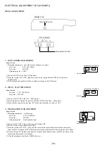
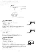
1.FOCUS BAIS ADJUSTMENT
1) Connect the digital multi-meter to the test point FE and Vref.
2) Play back the 2nd track of TCD-782.
3) Adjust SFR430 until the digital multi-meter indicates 0±10mV.
2.RF WAVEFORM CHECK
1) Connect oscilloscope to the test point RF SW and Vref.
2) Play back the 2nd track of TCD-782.
3) Check that the RF waveform has the maxmum amplitude and the center of the wedge waveform has
the clear blank.
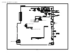
CD PWB
PATTERN SIDE
PARTS SIDE
SFR430
FE
R401
1
2
1 2 3
5
3
IC401
IC402
R402
IC403
Vref
RF SW
1
V
DIGITAL MULTIMETER
FE
Vref
OUTPUT
OSCILLOSCOPE
RF SW
Vref
VOLT / DIV: 500mV
TIME / DIV: 0.2 s
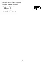
EYE PATTERN
must be CLEAR and MAX
Approx.
1.8 0.3Vp.p
Summary of Contents for XR-M161HS(S)
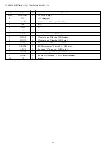
Page 23: ... 22 FL ZCL 8 GRID ASSIGNMENT ANODE CONNECTION 1 1 GRID ASSIGNMENT ANODE CONNECTION ...
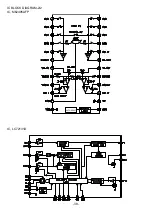
Page 39: ... 38 IC M62495AFP AUTO RESET IC BLOCK DIAGRAM 2 2 IC LC72131D ...
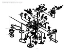
Page 51: ... 50 CD MECHANISM EXPLODED VIEW 1 2 DA 11T3C A M2 PIN 3 SW1 MOTOR C B 4 3 2 1 ...
Page 53: ... 52 CD MECHANISM EXPLODED VIEW 2 2 KSM 213CDM 1 2 COVER 3 4 5 SPINDLE MOTOR M3 MOTOR C B A M2 ...


