background image

INSTALLATION

                   Deep hood

                   (to prevent rainwater entering 

                   the system)

EA (

Exhaust 

       Outlet)

Maintenance Cover

Supply Air Grille

(Supply Air) (Exhaust Air)

Return Air Grille

SA

RA

Air Duct

Anchor bolt (to the provided by user)

OA (Outdoor

      Air Inlet)

1- Install the electric heater at a distance of two times away from 

duct connection diameter.

2- Connect the drainage line with downward slope.
3- Water condensed in the exchanger should be discharged by 

connecting 10mm. diameter drain hose to the drain outlet

under the unit.

4- The applications which can prevent the flow of 

water in the drainage line should be avoided.

5- The drainage line shall never be moved to an 

upper level than the drain pan.

Extremely Sharp Bends

Multiple Bends

Bends right next

to the outlet

Extreme Reduction in the

diameter of the connected ducts

Check these warnings 

before installation.

7

+30.211.70.55.500         +30.210.22.23.283

Summary of Contents for ENERGY BOX - TO 1.400

Page 1: ...Assembly Maintenance Guide 350 800 900 1 400 1 800 2 400 2 800 3 500 4 600 5 700 Ceiling Type Heat Recovery Unit Aluminium Plate ENERGY BOX TO 100 5 700 m3 h ...

Page 2: ...ge 16 Page 17 Introduction Warnings Safety Information Check List Technical Specifications Unit Dimensions Installation Alternatives Installation Selection of Electrical Cable Cross Section Electrical Connection Maintenance Control Panel 2 30 211 70 55 500 30 210 22 23 283 ...

Page 3: ... it properly and securely Use the designated electrical wires for the terminal board connections and connect the wires securely so that they will not be disconnected Failure to ensure proper connections may result in fire When passing metal ducts through wooden buildings clad with metal laths wire laths or metal these ducts must be installed in such a way that they will not make electrical contact...

Page 4: ...if there is incorrect connection In extremely cold climate applications frost may occur on the exchanger apply electric heater in fresh air intake section of the unit to get the temperature to 8 C and above After installing the unit make sure that it does not create an abnormal sound or vibration if there is make sure that rubber pads are used Please check whether the diameter of the air duct conn...

Page 5: ...stalsobeinsulatedagainstcondensation UNIT DIMENSIONS 350 800 900 1 400 1 800 2 400 2 800 3 500 4 600 5 700 Air Flow m h ENERGY BOX TO 350 780 930 1 440 1 800 2 440 2 780 3 500 4 650 5 735 230 50 1 96 204 310 450 450 1 030 1 030 940 1 360 2600 0 44 0 9 1 36 2 2 4 5 4 5 4 1 6 11 6 41 43 43 59 80 99 120 125 155 175 1 2 3 3 5 7 8 10 13 16 2 9 4 3 6 4 8 3 11 4 14 2 17 22 8 26 9 G Class Synthetic Filter...

Page 6: ...tion Opening S Electrical Pre Heater Optional 2 x ø d min 2 x ø d min ØD ØD Duct Type Electrical Heater Optional RA Return Air Grille S SA Supply Air Grille EA Exhaust Outlet OA Outdoor Air Inlet Maintenance Area Maintenance Area Inspection Opening S Electrical Pre Heater Optional 2 x ø d min 2 x ø d min ØD ØD Duct Type Electrical Heater Optional RA Return Air Grille S Alternative 1 Alternative 2 ...

Page 7: ... drainage line with downward slope 3 Water condensed in the exchanger should be discharged by connecting 10mm diameter drain hose to the drain outlet under the unit 4 The applications which can prevent the flow of water in the drainage line should be avoided 5 The drainage line shall never be moved to an upper level than the drain pan Extremely Sharp Bends Multiple Bends Bends right next to the ou...

Page 8: ...g the duct connection Flanges Hang the unit on the anchor bolts and adjust in such a way that the unit is installed horizontally Tighten up securely using double nuts in ordertoprevent looseness Hang the unit on the anchor bolts and adjust in such a way that the unit is installed horizontally Tighten up securely using double nuts in ordertoprevent looseness ENERGY BOX 350 3 500 ENERGY BOX 4 650 5 ...

Page 9: ...on table so that the equivalent ampere value in the table should be higher than selected I fuse value e 3 e 3 S1 1 5 mm 1 1 P I U S k L e Power Current Voltage Conductor cross section Conductor coefficient Conductor length The voltage drop 2 2 3 3 P 2600 W 100 P L 100 2600 50 100 P L U CosQ 230 0 8 k S U 56 3 230 k e U P U PF L e k 2 6 kW 230V CosQ 0 8 50m 3 56m Unit Model Unit Voltage V Unit Powe...

Page 10: ...with connecting control panel s A and B terminals as shown If these is an electric heater the connectors which are tagged as R S T must be supplied by three phase energy Setting the fan speed switch is Mains connection ENERGY BOX units connected to switch the fan speed setting WARNING Grid connection must be done to the L and N R S T if necessary terminals A and B terminals are room control panel ...

Page 11: ...5 4A BS95 3A BS95 7A BS95 6A CONNECTOR CONNECTOR KONDANSATOR TERMINAL KONTAKTÖR SWITCH KLEMENS REZİSTANS TOPRAKLAMA KLEMENS Molex 2 x 8 5557 type KONTROL P ANELİ ELEKTRİKLİ ISITICI ELEKTRİKLİ ISITICI BAĞLANTISI KONTROL KAR TI NOT KONTROL P ANELİ İLE CİHAZ ARASINA 2X0 75 BLEND AJLI KABL O ÇEKİNİZ KABLO UZUNL UĞUNUN 80M Yİ AŞMADIĞINA VE BLEND AJIN T OPRAKLANDIĞIND AN EMİN OLUNUZ KONTROL P ANELİ BAĞL...

Page 12: ... CONNECTOR CONNECTOR KONDANSATOR TERMINAL KONTAKTÖR SWITCH KLEMENS REZİSTANS TOPRAKLAMA KLEMENS Molex 2 x 8 5557 type CONTROL PANEL SITE CONNECTION CONTROL CARD SITE CONNECTION SITE CONNECTION SITE CONNCETION ELEC TRICAL HEATER DIAGRAM ELECTRIC HEATER 1 2 3 EXHAUST SUPPLY AIR CONTROL PANEL CONNECTION Only qualified service may intervene in the unit s internal connection WARNING 25 GROUNDED STEP ST...

Page 13: ...ER STEP 3 STEP 2 STEP 1 ENERGY BOX 4 650 N T 2 3 0 V H I G H M E D I U M L O W 2 4 V N 2 4 3 6 5 7 1 380 V The figure shows VECTOR control panel in ENERGY BOX 4 650 unit which is used with 3 stepped three phase electric heater Wire and grid connections must be done for the places with SITE CONNECTION expression ENERGY BOX 4 650 L1 L1 L1 L2 L2 L2 L3 L3 L3 Only qualified service may intervene in the...

Page 14: ...ater 2 phase these connections will not be made MAIN SUPPLY FAN STEP SET TRANSFORMER ENERGY BOX 4 650 3 STEPS ELECTRIC HEATER AUTOMATION DIAGRAM HRV The figure shows VECTOR control panel in ENERGY BOX 4 650 unit which is used with 3 stepped three phase electric heater WARNING Only qualified service may intervene in the unit s internal connection 14 30 211 70 55 500 30 210 22 23 283 ...

Page 15: ... FAN GND 1 0 0 1 GND T S R 80 70 60 50 LIMIT THERMOSTAT L1 L2 L3 1 2 3 4 G 1 0 R S T 1 2 3 4 BMS ON OFF BMS UNIT ON OFF R S T N R S T N A B A B L N C L N C ENERGY BOX 5 735 ELECTRICAL WIRING DIAGRAM MAIN SUPPLY STEP 1 ELECTRIC HEATER CONTROL PANEL CONTROL CARD 25 WARNING Only qualified service may intervene in the unit s internal connection GROUNDED ELETRICAL CONNECTIONC 15 30 211 70 55 500 30 210...

Page 16: ...t the air filter to protect the components of the unit against being clogged Clean up the air filter more than once in a year Clean up the heat exchanger more than once per year Step 2 Heat exchanger can be cleaned by hot water or steam Leave to dry after cleaning heat exchanger Connect the unit after making sure that the heat exchanger has dried Step 2 Use a vacuum cleaner to suck up the dust fro...

Page 17: ...hts up Aftera5secondsdelaythemodewillbeactivated Thetext MODEondisplayisalwaysvisible MODE FAN COOL HEAT AUTO VOD Shows active mode of operation FAN HIGH MED LOW 12 00 25 C 0 BY PASS FUNCTION FILTER CHECK EXHAUST FAN SUPPLY FAN SET TEMP MON TUE WED THU FRI SAT SUN SET Only visible when changing fan speed Shows current day Actual time or timer block s Actual room temp or set point Shows actual fan ...

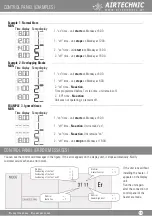
Page 18: ...t 18 00 Example 1 Normal blocs Example 2 Overlapping Blocks EXAMPLE 3 Ignored times 2 on time No action Time programmed before 1st stop time unit remains off 2 off time No action Unit was not operating so remains off No Error No Error No Error Heater High Limit Faulty Fan No Error Heater Control Overheating of the fan 1 Overheating of the fan 2 Overheating of the fan 1 and 2 You can see the contro...

Page 19: ...igh Med and Low fan speeds can be selected by pressing FAN button Bypass damper In COOL mode the damper valve will be controlled in accordance with T1 return air and T2 outdoor air sensors During the winter season the HEAT mode either can be manually selected with the remote control or automatically controlled via the Fan The default speed of the fan is medium If necessary press FAN button to chan...

Page 20: ...S FAN COIL UNITS AIR FILTERS AIR FILTERS AIR CONDITIONING VENTILATION COMPONENTS SYSTEMS STEAM HUMIDIFIERS DEHUMIDIFIERS ATHENS Michail Karaoli 19 14343 Nea Chalkidona Athens Τel 30 211 70 55 500 30 210 21 30 051 Fax 30 210 22 23 283 sales airtechnic gr THESSALONIKI End of Maiandrou extension 57013 Oraiokastro Thes nikis Τel 30 2311 824 000 thessaloniki airtechnic gr ...

Reviews: