background image


18120511-01 

Airspan Networks Inc. 

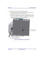
Resetting EasyWiFi 

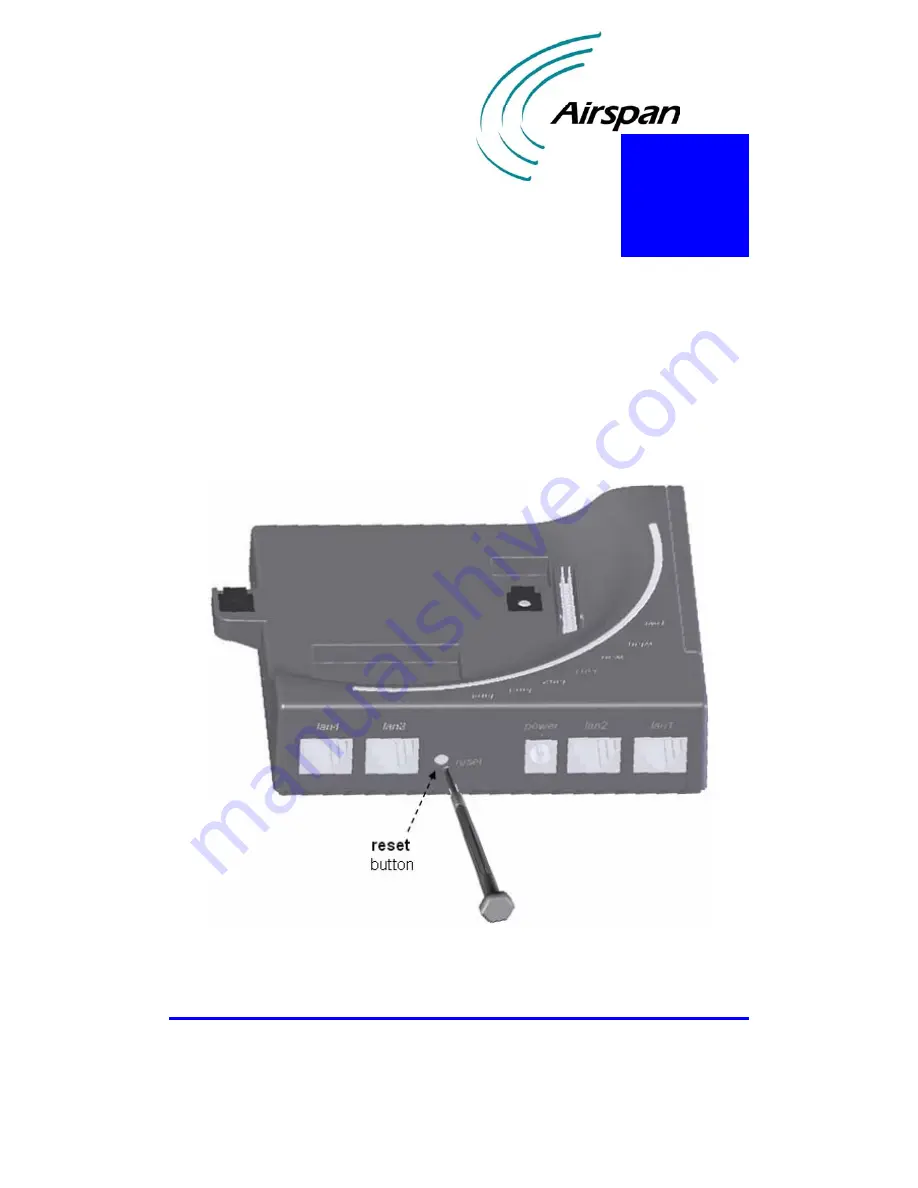
The EasyWiFi provides a button that enables you to reboot the EasyWiFi as well as 
reset the EasyWiFi settings to default. This button is located on the EasyWiFi's back 
panel and labeled 

reset

To reboot or reset to default the EasyWiFi: 

1.


Using a tool with a pointed edge, insert the edge into the hole labeled 

reset


(located on the back panel next to the DC power jack). 


Figure 


7-1:  Resetting EasyWiFi to default using reset button 

Summary of Contents for EasyWiFi

Page 1: ...IP based Broadband Wireless Access BWA System EasyWiFi WiFi Extension Module for the EasyST Unit Hardware Installation Guide The Innovation Behind Broadband Wireless Connecting the World ...

Page 2: ......

Page 3: ...sibility is assumed by Airspan Networks Inc for the use thereof nor for the rights of third parties which may be effected in any way by the use thereof Any representation s in this document concerning performance of Airspan Networks Inc product s are for informational purposes only and are not warranties of future performance either express or implied Airspan Networks Inc standard limited warranty...

Page 4: ...EasyWiFi ...

Page 5: ...This page is intentionally left blank ...

Page 6: ...2 4 Mounting Parts 2 5 2 5 LEDs 2 6 3 Attaching EasyST 3 1 4 Connecting to LAN 4 1 5 Mounting 5 1 5 1 Desktop Mounting 5 2 5 2 Wall Mounting 5 3 6 Connecting Power 6 1 6 1 Changing the AC DC Power Adapter s Prongs 6 2 6 2 Connecting AC DC Power Adapter 6 3 7 Resetting EasyWiFi 7 1 A FCC Interference Statement A 1 B Glossary B 1 C EasyWiFi Specifications C 1 D Power Adapter Specifications D 1 ...

Page 7: ...EasyWiFi Contents 18120511 01 Airspan Networks Inc ii This page is intentionally left blank ...

Page 8: ...is intended for the end user installing the EasyWiFi extension module for the EasyST This device requires no professional installation Typographical Conventions This guide uses the following typographical conventions Convention Meaning Example Bold Command menu icon button and field Click the Next button To in bold face and at the beginning of a sentence Introduces a numbered procedure To download...

Page 9: ...service and support for your EasyWiFi contact your regional Airspan representative or Airspan s Technical Assistance Center TAC at Web site Support Request Form http www airspan com Ultra ContactForm airspansupportform asp Americas 1 561 893 8679 International 44 1895 467 467 ...

Page 10: ...tches 10 100BaseT DC power The EasyST is easily plugged onto the EasyWiFi extension module by means of a 30 pin IDC connector The EasyWiFi is powered by an AC DC adapter that is plugged directly into a standard electrical wall outlet 110 220 VAC In addition the adapter s plug prongs can be easily removed and then replaced to suite electrical sockets of the country in which the unit is being instal...

Page 11: ...EasyWiFi Introduction 18120511 01 Airspan Networks Inc 1 2 This page is intentionally left blank ...

Page 12: ...s a physical description of the EasyWiFi extenson module 2 1 Physical Dimensions The physical dimensions of the EasyWiFi are listed in the table below Table 2 1 EasyWiFi physical dimensions Parameter Value Dimensions height x width x length 30 x 125 x 125 mm Weight 210 grams 2 ...

Page 13: ...2 2 Easy WiFi port descriptions Port Label Interface 8 pin RJ 45 x four lan1 lan2 lan3 lan4 10 100BaseT Ethernet LAN DC power jack power 6 VDC power supplied by AC DC power adapter Reset button reset Resets configuration settings to factory default 30 pin IDC socket Interfaces with EasyST providing 802 11 Wi Fi LAN switches DC power Note IDC socket accepts flat cables ...

Page 14: ...EasyWiFi Physical Description 18120511 01 Airspan Networks Inc 2 3 Figure 2 1 display the EasyWiFi ports Figure 2 1 EasyWiFi ports side and top panels ...

Page 15: ...iFi provides an integral WiFi antenna located on its side panel that can be orientated in the vertical pane from 0 i e antenna closed to 180 Two positions are used 90 when EasyWiFi mounted horizontally and 180 when EasyWiFi mounted vertically on a wall Figure 2 2 EasyWiFi integral WiFi antenna ...

Page 16: ...works Inc 2 5 2 4 Mounting Parts The EasyWiFi unit provides built in wall mounting brackets desktop mounting feet as well as locking latches for mounting attaching the EasyST to the EasyWiFi extension module Figure 2 3 EasyWiFi mounting parts bottom panel ...

Page 17: ...511 01 Airspan Networks Inc 2 6 2 5 LEDs The EasyWiFi provides LEDs for indicating the status of various operations These LEDs are located on the top panel for easy viewing as shown in the figure below Figure 2 4 EasyWiFi LEDs top panel ...

Page 18: ...wer Red Off No power On WiFi link with one user or more Flashing Active WiFi link i e data transfer wlan Green Off No WiFi link On Link EasyST and EasyWiFi is active Activity in 10Mbps Blinks at 3Hz Flashing Activity in 100Mbps Blinks at 12 Hz wan Green Off EasyST is not connected On 10 100BaseT network device e g PC is on Flashing Active LAN link i e traffic flow lan1 lan2 lan3 lan4 Green Off No ...

Page 19: ...EasyWiFi Physical Description 18120511 01 Airspan Networks Inc 2 8 This page is intentionally left blank ...

Page 20: ... a 30 pin connector located on the EasyWiFi s top panel For securing the connection of the EasyST to the EasyWiFi the EasyWiFi provides two latches that locks and unlocks the EasyST from the EasyWiFi The latches are located on the EasyWiFi s bottom and side panels Figure 3 1 EasyST attached to EasyWiFi 3 ...

Page 21: ...T with the EasyWiFi by aligning the following EasyST 30 pin female connector with EasyWiFi s 30 pin male connector EasyST RJ 45 port with EasyWiFi RJ 45 port labeled lan2 2 Press the EasyST firmly onto the EasyWiFi so that the 30 pin connectors contact and plug into one another Figure 3 2 Aligning EasyST with EasyWiFi ...

Page 22: ...the latch towards the locking direction indicated by the lock label b On the bottom side panel use a tool with a pointed edge to move the latch into the EasyST s mounting bracket by inserting the pointed egde into the latch s hole and then dragging the latch into the EasyST s mounting bracket until it is firmly in place Figure 3 3 EasyWiFi latches unlock position ...

Page 23: ...EasyWiFi Attaching EasyST 18120511 01 Airspan Networks Inc 3 4 Figure 3 4 EasyWiFi latches lock position ...

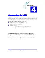
Page 24: ... mode Auto Negotiation and Auto MDIX The EasyWiFi to computer cable setup is listed below Cable straight through CAT 5 STP Ethernet cable Connector 8 pin RJ 45 at both ends Connector pinouts Pin Function 1 Tx 2 Tx 3 Rx 6 Rx To connect EasyWiFi LAN ports to the subscriber s Ethernet network 1 Plug the Category 5 Ethernet cable into the desired EasyWiFi 8 pin RJ 45 port 2 Plug the other end of the C...

Page 25: ...EasyWiFi Connecting to LAN 18120511 01 Airspan Networks Inc 4 2 The figures below illustrate the EasyWiFi to computer cable connection Figure 4 1 Connecting EasyWiFi to subscriber s LAN ...

Page 26: ...in a location that provides the following High quality RF reception with the Internet service provider i e base station Accessibility to subscriber s power supply and LAN network with regards to cable lengths Strong radio signal strength for the WiFi communication link between EasyWiFi and the subscriber s WiFi computer EasyWiFi can be mounted in the following ways depending on the EasyST s antenn...

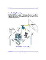
Page 27: ...fers quick and easy mounting by allowing you to simply place it horizontally on a desktop as shown in the figure below The EasyWiFi contains integrated rubber feet pads on its bottom panel providing cushioning as well as insulation from static electricity Figure 5 1 Desktop mounting EasyWiFi ...

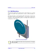
Page 28: ...top mounting or a wall The figure below shows a wall mounted EasyWiFi The EasyST is connected to an RF cable that connects to the external antenna i e clip on antenna is removed For mounting to a wall the EasyWiFi provides two mounting hooks molded into its bottom panel as shown below Figure 5 2 Wall mounted EasyWiFi Note The EasyWiFi s WiFi antenna must be fully extended i e 180 degrees when wall...

Page 29: ... which the two EasyWiFi mounting hooks will later by guided The distance between the two wall mounting hooks from their centers is approxiamtely 83 mm 3 27 inches Ensure that the holes are aligned and level using a spirit level 2 Drill holes for each hole that you marked in the step above using a no 6 twist drill bit 3 Tap the 6 mm wall anchors supplied into each of the drilled holes ...

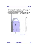
Page 30: ...t at least 0 08 inch gap is exposed between the screw head and the wall anchor to allow insertion into the EasyWiFi mounting hooks 5 Align the screws with the entrance to the two EasyWiFi mounting hooks and then pull down the EasyWiFi to lock the screws into the mounting hooks Figure 5 3 Inserting screws into wall mounting hooks ...

Page 31: ...EasyWiFi Mounting 18120511 01 Airspan Networks Inc 5 6 This page is intentionally left blank ...

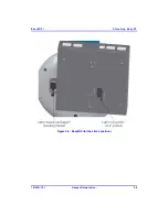
Page 32: ...ngeable prongs e g American vs European that can be replaced to suit country electrical standards in which the EasyWiFi is being installed To view the AC DC power adapter specifications see Appendix C Power Adapter Specifications Note Any AC DC power adapter complying with Class 2 and LPS and safety approved according to national regulations and that provides rated input of 100 240 V 50 60 Hz 0 4 ...

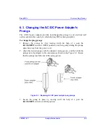
Page 33: ...gs by first moving with the help of a pen the LOCK OPEN switch to OPEN position and then gently sliding the prongs upwards away from the power cord 2 Align the desired prongs with the adapter s prong groove and then slide the prongs onto the adapter in the orientation as shown in the Figure 6 1 Ensure that the prongs reach the end of the prong groove Figure 6 1 Replacing AC DC power adapter plug p...

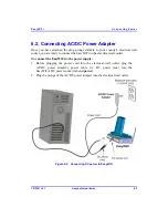
Page 34: ...eady to connect the EasyWiFi to the electrical wall outlet To connect the EasyWiFi to the power supply 1 Before plugging the power cord into the electrical wall outlet plug the AC DC power adapter s power cable i e DC power jack into the EasyWiFi s DC power socket labeled power 2 Plug the prongs of the AC DC power adapter into the electrical wall outlet Figure 6 2 Connecting DC power to EasyWiFi ...

Page 35: ...EasyWiFi Connecting Power 18120511 01 Airspan Networks Inc 6 4 This page is intentionally left blank ...
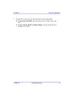
Page 36: ...et the EasyWiFi settings to default This button is located on the EasyWiFi s back panel and labeled reset To reboot or reset to default the EasyWiFi 1 Using a tool with a pointed edge insert the edge into the hole labeled reset located on the back panel next to the DC power jack Figure 7 1 Resetting EasyWiFi to default using reset button 7 ...

Page 37: ...n Networks Inc 7 2 2 Push the the tool into the hole until you feel a button being pushed To reboot the EasyWiFi push the button once and then remove the tool To reset the EasyWiFi to default settings keep the button pressed for at least 7 seconds ...

Page 38: ...evision reception which can be determined by turning the equipment off and on the user is encouraged to try to correct the interference by one of the following measures Reorient or relocate the receiving antenna Increase the separation between the equipment and receiver Connect the equipment into an outlet on a circuit different from that to which the receiver is connected Consult the dealer or an...

Page 39: ...lies with FCC radiation exposure limits set forth for an uncontrolled environment This equipment should be installed and operated with minimum distance 20cm between the radiator your body This transmitter must not be co located or operating in conjunction with any other antenna or transmitter ...

Page 40: ... Gateway HTTP HyperText Transfer Protocol Hz Hertz IP Internet protocol ISP Internet Service Provider LAN Local Area Network MAC The next layer up from the PHY known as the media access controller Mbps Megabits per second one million bits per second MHz Megahertz one million cycles per second MIB Management information base ODU Outdoor unit associated with an ST QAM Quadrature amplitude modulation...

Page 41: ...nt protocol SNR Signal to noise ratio ST Subscriber terminal interchangeable with CPE SW Software Tx Transmit VoIP Voice over Internet protocol WiFi Wireless Fidelity WiMAX WiMAX is a wireless industry coalition whose members are organized to advance IEEE 802 16 standards for broadband wireless access BWA networks ...

Page 42: ...panese Standard ARIB STD T66 WiFi antenna Gain 1 dBi Clients No of concurrent assigned users 1 024 No of concurrent active users 32 Radio technology Tx power max 19 dBm Networking Working modes Bridge default and IP router modes Interfaces Four 10 100BaseT Ethernet LAN support Half Full duplexing Auto Negotiation Auto MDIX with subscribers network Radio with EasyST 30 pin IDC connector DC power De...

Page 43: ...peratures 20 to 75 C ambient Operating Humidity 15 90 RH Environmental Conditions Storage Humidity 5 95 RH Ports WiFi antenna 4 x 8 pin RJ 45 Ethernet LAN ports Half Full duplexing Auto Negotiation Auto MDIX DC power socket 30 pin IDC connector Button for reset LEDs for LAN WAN WiFi Power Mounting 2 x wall mounting brackets 2 locking clips for attaching EasyST Power requirements Input Voltage Ampe...

Page 44: ... VAC Input Earth leakage 0 4 mA max 115 VAC 0 8 mA max 230 VAC Output rating 6V 4A Output voltage accuracy 2 max Max output power 24W Line regulation 1 max Load regulation full to half load 6 6 5V Transient response full to half load 1 max dev 500 uS recovery Temperature coeffeicient 0 04 C Ripple and noise 100mVp p max Output Protections Over voltage protection output voltage 7 5V Over power prot...

Page 45: ...ut Ground 1500 Vac Safety meet UL CUL UL60950 CE EN55022 Switching frequency 100 kHz Connector for radio Input interchangeable prongs Output DC power jack Cable length 1 25 m Dimensions 86 46 33 mm Weight 180 g MTBF 100 000 hours MIL HDBK 217F Operating temperature 0 to 40 C Storage temperature 20 to 85 C Humidity 5 to 95 RH non condensing Vibration 2 4G 5 to 500 Hz Environmental Cooling Free air ...

Page 46: ...EasyWiFi Power Adapter Specifications 18120511 01 Airspan Networks Inc D 3 This page is intentionally left blank ...
Page 47: ...s products and solutions please visit our Web site www airspan com Or write to us at one of the addresses below We will be delighted to send you additional information on any of our products and their applications around the world Worldwide Headquarters Airspan Networks Inc 777 Yamato Road Suite 105 Boca Raton Florida 33431 4408 USA Tel 1 561 893 8670 Fax 1 561 893 8671 Main Operations Airspan Com...

Reviews: