AirSource CustomAir Installation, Operation & Maintenance Instructions Manual Download Page 18


17 


Installation, Operation & Maintenance Manual 

fgfgffhfgfggbffgfV11:0212212121 

 
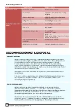
Fault Finding Continued: 


DECOMMISSIONING & DISPOSAL 


Fault


Possible Cause 

Remedy / Action 

No heating or cooling 


Temperature controller. 

Contact controls specialist. 


No air volume. 
 

Inspect drive belts. Check motor winding 
resistance. 

Pressure switch failure. 

Inspect fan pressure switch and tubing, 
replace as necessary. 

Refrigeration fault. 

Contact refrigeration specialist. 

Low heating output or Air 
Volume 

Compressor fault indication. 
 

Contact refrigeration specialist. 

Dirty filters. 


Replace filters. 


Defective Heat Recovery device. 
 

Thermal Wheel: 
Check wheel rotation. 
Recuperator: 
Check  bypass  damper  closed  on  heating 
demand. Replace if faulty. 

Frost coil not operational (if 
applicable). 


Contact controls specialist. 
 

Re-heat coil not operational. 
 

Investigate operation of control valve. 
 

Seasonal  Shutdown 


Before an extended period of non-use, it is recommended to reduce the system to 
minimum


capacity using the regulation/control system, then set any dampers to run 

in a recirculating arrangement (if applicable) in order to reduce risk of frost. 

It is also advisable to close all control valves, then switch off any recirculating 
pumps, followed by closing all fresh water and manual valves. Small empty spaces 
suffer from a risk of frost, so it is a good idea to blow compressed air through them, if 
available, until they are free from residue. 


Allow the fan to run until all surfaces are dry. Switch off the mains switch and lock 
everything up. 


If the unit is not to be used for several months and the fan(s) have a belt (most non-
EC fans), then it is advisable to either slacken or remove the fan belt to avoid 
tensioning damage during storage. 

End of Life Disassembly 


Before starting disassembly, the AHU and all built-in components must be 
disconnected from the mains and all live connections removed by a qualified 
electrician. Additionally, all media-bearing components must be completely emptied. 

This must be conducted by a specialized company which can carry out the 
professional disposal of water with antifreeze, and refrigerants. 


The AHU can then be dismantled on-site into individual unit modules or into its 

component parts. It is advisable for this to be carried out by a specialized company, 
familiar with the environmentally friendly disposal of all component parts.  


Summary of Contents for CustomAir

Page 1: ... OPERATION MAINTENANCE INSTRUCTIONS Custo Air Handling Units Email TempAir AirSource Heatpumps INSTALLATION OPERATION MAINTENANCE INSTRUCTIONS CustomAir Air Handling Units Tel 0161 425 8553 Fax 0161 637 0232 Email info air source net TempAir AirSource Heatpumps ...

Page 2: ...Maintenance 15 WARRANTY DELIVERY INSTALLATION General COMMISSIONING TESTING MAINTENANCE HEALTH SAFETY General Cautionary Notes Water treatment 3 3 3 Heating Cooling Coils 12 Invalidation of Warranty 3 8 Electrical Connections 8 Ductwork Connections Procedure 2 2 Safety symbols 3 7 Assembly of Multiple Sections 8 Motor Wiring Diagrams 9 Pipework Connections 9 Water Coils Steam Coils DX Coils 10 Con...

Page 3: ...s checks may be required to be carried out prior to our engineer s attendance at site A purchase order number in the event that the fault is not covered under the terms of the warranty An engineer will be scheduled to attend at the earliest availability to carry out an inspection repair of the fault reported Our response will depend on the availability of an engineer and the parts required to carr...

Page 4: ... the hazards that could be encountered when any work is carried out on the equipment for which this manual is written Therefore the following points should be observed to avoid any injuries or health hazards The installation of the unit shall be checked to ensure that A suitable electrical supply is connected Prior to entry to any section please ensure that the electrical supply isolated either at...

Page 5: ...ance Manual oints Longer straps will reduce the sideways force applied to the roof and help prevent damage to the unit Use of spreader beams is recommended to prevent damage to the sides of the AHU Use of spreader beams is recommended to the AHU all straps chains should be vertical during lift IMPORTANT Ensure the forks extend beyond the casing of the unit Upon receipt of equipment a visual inspec...

Page 6: ... stationary for too long periods The balls and races may suffer damage by fretting corrosion false brinelling stationary vibration or static vibration marking Belts Pulleys Wedge belts should be removed from the pulleys and hung up and not exposed to excessive heat or cold and kept free from dampness Belt life is reduced over a long period of non use due to the curing and static condition of rubbe...

Page 7: ...ommend an additional distance equal to the unit dth before any obstacle to prevent recirculation of the exhaust air into the fresh air All units must be installed in accordance with good engineering standards upright level on a prepared base Fixing down of air handling units is at the discretion of the installer and dependant of the site conditions Flexible connections are NOT recommended for conn...

Page 8: ...the unit using sash clamps or ratchet straps chains using the internal corner plates to aid alignment One section should slot into the other CAUTION Before drawing together ensure nothing will get trapped in the space between each section Once the unit has been pulled er install assembly bolts through the corner fixing plates on the inside of the unit For each corner tighten the bolts ensuring goo...

Page 9: ...rate the AHU casework ensure that the casework is adequately sealed to prevent air leakage water ingress If the unit is provided with package controls then always use the cable entry as provided USE THE CORRECT WIRING DIAGRAM AS DETAILED BELOW TO SUIT THE INCOMING MAINS VOLTAGE FAILURE TO DO SO MAY RESULT IN PERMANENT DAMAGE TO THE MOTOR CONTROL GEAR When inverters are provided fitted to the AHU t...

Page 10: ...lters are also Coils are normally designed as either cartridge arrangement where they are fitted inside the casework of the air handling unit or bolted directly between two sections of the AHU All LPHW and chilled water coils are fitted with an air vent and drain plug on the All cooling coils include a condensate drain tray fitted with a drain connection to be connected to an appropriate trapping ...

Page 11: ...g supply lines to the motor to change direction if required Set the inverter frequency as indicated on the HU general arrangement drawing AHU the following checks should be made Refer to General Arrangement drawing for specific details Isolate electric supply to f before entering the fan section Check for any visible damage to the fan impeller and mounting assembly vibration mountings are level an...

Page 12: ...rol panel an inverter control pad or through a software setting which can be set via touchscreen if applicable It is not recommended to run the unit in Test mode other than for air balancing purposes otherwise the unit will not operate correctly Inverters Fan inverters can be controlled via a control pad installed inside the control panel interior if applicable Generally there is a control pad for...

Page 13: ...environment number of hours run but should not be more than three monthly intervals On fans operating in dusty atmospheres or exposed to weather will need to be inspected and cleaned every 3 months If a fan is stationary for long periods in a humid atmosphere it should be switched on minimum of two hours every month to remove any moisture that may have condensed within the motor These should be wi...

Page 14: ...o the rotor surface In situations where self cleaning is not sufficient dependant on the degree of fouling the rotary wheel can be periodically cleaned with compressed air or high pressure water room temperature water only belt is designated SPZ or SPA and is commercially supplied with the belt Connection is done by flexible links Due to the fact that belt is subject to natural stretching which ma...

Page 15: ...ved through the access door by simply sliding the filter out along the channel runner as shown below unlocking before removal To remove gently turn the screw grips as shown highlighted in the red box above at the top of the bag filter anti clockwise then when the screw has been loosened enough twist the locking mechanism horizontally to allow room for the bag filter to be removed with ease Filters...

Page 16: ...s shared by the end user and the appointed maintenance engineers Failure to comply with the F Gas regulations will result in invalidation of the warranty on the refrigeration system within the unit Safety Warning Ensure that all power to the unit is switched off before carrying out any servicing or maintenance task Only trained and qualified service personnel should repair or service air condition...

Page 17: ...cks should be carried out Check the suction and discharge pressures using a service gauge manifold and compare them with the commissioning sheet If there is any significant variation then the fault should be found and corrected Refer to the troubleshooting chart If on inspection of the refrigeration pressures a refrigerant leak is suspected open all access panels to ensure the gas has dissipated t...

Page 18: ...icable in order to reduce risk of frost It is also advisable to close all control valves then switch off any recirculating pumps followed by closing all fresh water and manual valves Small empty spaces suffer from a risk of frost so it is a good idea to blow compressed air through them if available until they are free from residue Allow the fan to run until all surfaces are dry Switch off the main...

Page 19: ...oved by loosening the fixings as per the normal maintenance process then recycled Panel filters are comprised of paper cardboard synthetic felt polymer and steel wire frame Bag filters have a steel frame with felt polymer comprising the main body of the filter and thus must be additionally separated into individual components for most recycling centres Refrigeration Refrigeration circuits MUST be ...

Page 20: ...ely recyclable some sensors such as gas sensors and pressure transducers may contain circuit boards which must be disposed of according to the WEEE Waste Electrical and Electronic Equipment directive inside Europe or relevant RoHS directives Control panel Within the United Kingdom and Europe the majority of electronic components within the control panel will be required to be sent to an accredited...

Reviews: