


9
Installation, Operation & Maintenance M
fgfgffhfgfggbffgfV11:0212212121
DX Coils
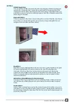
When brazing close to the AHU
pipework seals. Following completion of the refrigeration installation, a nitrogen
pressure test should be carried out on the system. All refrigerant coils should be
vacuum dehydrated after installatio
Steam
Ensure that installation is correct to provide adequate drainage of co
Coils
prevent water
hammer, freezing and corrosion within the coil and pip
Ensure that the AHU is level to avoid condensate being held wi
use of flexible connections or swing joints is recommended. Adequate condensate traps
should be provided on each coil section and be trapped separately. Fluid filters are also
recommended.
Water
General
Coils
Coils are normally designed as either cartridge arrangement where they are fitted inside
the casework of the air handling unit, or bolted directly between two sections of the
AHU. All LPHW and chilled water coils are fitted with an ai
header connections.
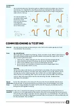
Drain Connections
All cooling coils include a condensate drain tray fitted with a drain connection to be
connected to an appropriate trapping system. Care must be taken to ensure that the
correct type of drain trap is used depending on positive / negative air pressure within
the coil section (see condensate drains section).
Drain lines from the trap must be pitched downwards, a slope of 1:25 is recommended.
Ensure that the water flow & return connections ar
entering the coil on the leaving
Frost protection
Water systems should be provided with a suitable anti
freezing. Fluid filters are also
Pipework
The installer should ensure that all pipework is of the correct s
Pipework must not block or restrict access to any doors or access panels.
Care must be taken to ensure the foll
•
Water flow & return connections are correctly connected.
•
All connecting pipe
•
Any pipe movement caused by expansion or contraction must be absorbed by
flexible joints.
•
Coils located at high points of the system should be regularly vented,
otherwise coils may become air locked causing a reduction in duty.
•
When connecting screwed fittings, it is necessary to restrain the back nut to
avoid damage to the coil.
Installation, Operation & Maintenance Manual
When brazing close to the AHU casework, take care not to cause damage to the paint or
pipework seals. Following completion of the refrigeration installation, a nitrogen
pressure test should be carried out on the system. All refrigerant coils should be
vacuum dehydrated after installation.
Ensure that installation is correct to provide adequate drainage of condensate to
hammer, freezing and corrosion within the coil and pipework system.
is level to avoid condensate being held within the coil tubes. The
use of flexible connections or swing joints is recommended. Adequate condensate traps
should be provided on each coil section and be trapped separately. Fluid filters are also
Coils are normally designed as either cartridge arrangement where they are fitted inside
the casework of the air handling unit, or bolted directly between two sections of the
AHU. All LPHW and chilled water coils are fitted with an air vent and drain plug on the
All cooling coils include a condensate drain tray fitted with a drain connection to be
connected to an appropriate trapping system. Care must be taken to ensure that the
ain trap is used depending on positive / negative air pressure within
the coil section (see condensate drains section).
Drain lines from the trap must be pitched downwards, a slope of 1:25 is recommended.
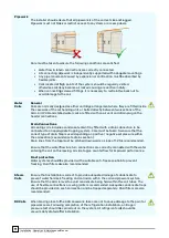
Ensure that the water flow & return connections are correctly connected with the water
entering the coil on the leaving-air side to give counterflow for improved performance.
Water systems should be provided with a suitable anti-freeze solution to prevent
freezing. Fluid filters are also recommended.
The installer should ensure that all pipework is of the correct size and
Pipework must not block or restrict access to any doors or access panels.
ensure the following conditions are satisfied:
Water flow & return connections are correctly connected.
All connecting pipework is independently supported with adequate
Any pipe movement caused by expansion or contraction must be absorbed by
Coils located at high points of the system should be regularly vented,
otherwise coils may become air locked causing a reduction in duty.
When connecting screwed fittings, it is necessary to restrain the back nut to
avoid damage to the coil.
asework, take care not to cause damage to the paint or
pipework seals. Following completion of the refrigeration installation, a nitrogen
pressure test should be carried out on the system. All refrigerant coils should be
ndensate to
ework system.
thin the coil tubes. The
use of flexible connections or swing joints is recommended. Adequate condensate traps
should be provided on each coil section and be trapped separately. Fluid filters are also
Coils are normally designed as either cartridge arrangement where they are fitted inside
the casework of the air handling unit, or bolted directly between two sections of the
r vent and drain plug on the
All cooling coils include a condensate drain tray fitted with a drain connection to be
connected to an appropriate trapping system. Care must be taken to ensure that the
ain trap is used depending on positive / negative air pressure within
Drain lines from the trap must be pitched downwards, a slope of 1:25 is recommended.
e correctly connected with the water
air side to give counterflow for improved performance.
freeze solution to prevent
ize and lagged.
Pipework must not block or restrict access to any doors or access panels.
ndently supported with adequate mountings.
Any pipe movement caused by expansion or contraction must be absorbed by
Coils located at high points of the system should be regularly vented,
otherwise coils may become air locked causing a reduction in duty.
When connecting screwed fittings, it is necessary to restrain the back nut to


