58
7.5 I/O Terminal Application
Typically used in association with programming scripts for developing applications for motion
detection, event triggering, alarm notification via e-mail, and a variety of external control
functions. The 6-pin I/O Terminal Block is located on the rear panel and provides the interface
to: a photo-coupled switch output, a photo-coupled input, and RS-485 interface. The RS-485 is
typically used for pan/tilt/zoom control.
Connector Pin Assignment
PIN No.
FUNCTION
SPECIFICATION
1
RS-485 (+) or (A)
2
RS-485 (-) or (B)
Compliant to RS-485
3 Photo-Relay
INPUT
(+)
4 Photo-Relay
INPUT
(-)
Active High voltage 9~40VDC
Dropout voltage 0 VDC
5 Photo-Relay
OUTPUT
(Normal Open)
6 Photo-Relay
OUTPUT
(Common)
Close circuit current maximum
70 mAAC, or 100 mADC.
Output resistance 30 Ohm.
Open circuit voltage maximum
240VAC or 350VDC
Monitoring and Controlling
By entering http requests in your browser’s URL field, you can:
‧
Monitor the status of digital input
‧
Drive the output switch on or off
‧
Control the speed/position of pan/tilt/zoom motors in a swivel stand or a speed dome
camera.
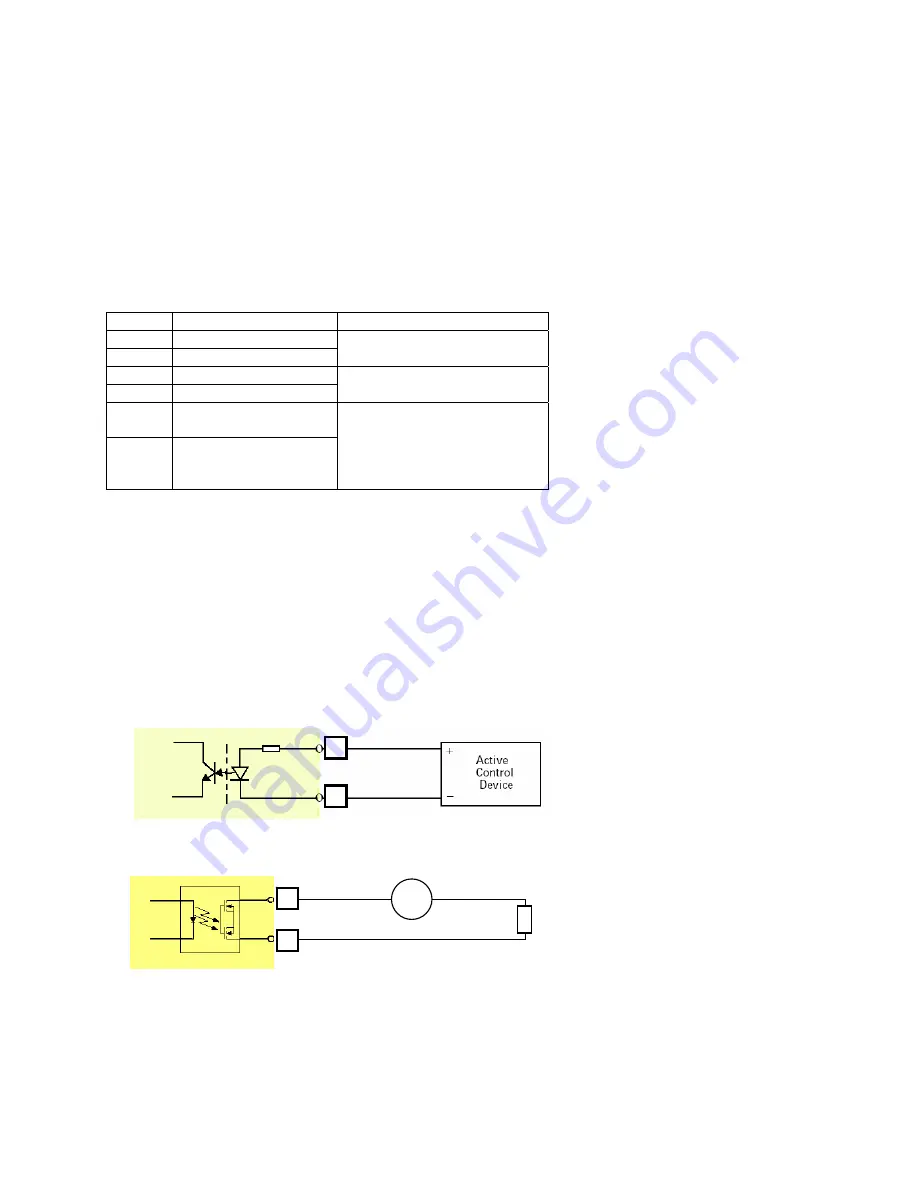
Interface Schematic
1. Input
device (active control device) has independent power supply.
2.
Output device (load) is driven by external power supply.
3.
RS485 Interface
3
4
5
6
AC/
DC
Load


