507206-01
Page 16 of 59
Issue 1337
Vent Piping Guidelines
This gas furnace can be installed as either a Non-Direct
Vent or a Direct Vent gas central furnace.
NOTE:
In non-Direct Vent installations, combustion air is
taken from indoors and flue gases are discharged outdoors.
In Direct Vent installations, combustion air is taken from
outdoors and flue gases are discharged outdoors.
Intake and exhaust pipe sizing
- Size pipe according
to Tables 6 and 7. Table 6 lists the
minimum
vent pipe
lengths permitted. Table 7A - 7C lists the
maximum
pipe
lengths permitted.
Regardless of the diameter of pipe used, the standard roof
and wall terminations described in section
Exhaust Piping
Terminations
should be used. Exhaust vent termination
pipe is sized to optimize the velocity of the exhaust gas as
it exits the termination.
Do not use screens or perforated metal in exhaust or
intake terminations. Doing so will cause freeze-ups and
may block the terminations.
IMPORTANT
In some applications which permit the use of several different
sizes of vent pipe, a combination vent pipe may be used.
Contact Allied Air Technical Service for assistance in sizing
vent pipe in these applications.
Table 6
The exhaust vent pipe operates under positive pressure
and must be completely sealed to prevent leakage of
combustion products into the living space.
CAUTION
Use the following steps to correctly size vent pipe diameter.
Figure 21
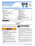
MINIMUM VENT PIPE LENGTHS
A95DF2E/95G2DFE
MODELS
MIN.VENT LENGTH*
045,070,090,110
15 ft or 5 ft plus 2 elbows or
10 ft plus 1 elbow
*Any approved termination may be added to the minimm length listed.
Summary of Contents for 95G2DFE
Page 3: ...507206 01 Page 3 of 59 Issue 1337 Figure 1 ...
Page 17: ...507206 01 Page 17 of 59 Issue 1337 A95DF2E 95G2DFE Table 7A ...
Page 18: ...507206 01 Page 18 of 59 Issue 1337 A95DF2E 95G2DFE Table 7B ...
Page 19: ...507206 01 Page 19 of 59 Issue 1337 A95DF2E 95G2DFE Table 7C ...
Page 27: ...507206 01 Page 27 of 59 Issue 1337 Figure 32 ...
Page 34: ...507206 01 Page 34 of 59 Issue 1337 Figure 48 TRAP DRAIN ASSEMBLY USING 1 2 PVC or 3 4 PVC ...
Page 36: ...507206 01 Page 36 of 59 Issue 1337 Figure 50 Table 10 ...
Page 40: ...507206 01 Page 40 of 59 Issue 1337 TYPICAL WIRING DIAGRAM Figure 54 ...
Page 56: ...507206 01 Page 56 of 59 Issue 1337 Start UP Performance Check List ...