REFRACTOR PROFESSIONAL OVERDRIVE
17
INPUT/OUTPUT PCB
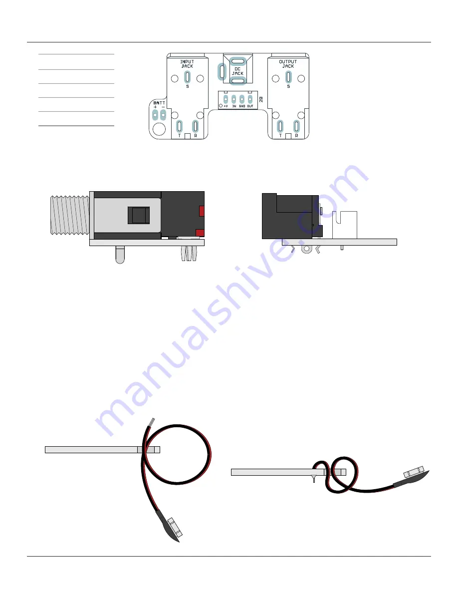
Almost done! Get the two input/output jacks, the DC jack and the wire header and snap them in place.
The PCB is designed for them to fit securely, so you can do them all at once before flipping and soldering.
After you’ve soldered everything, make sure to
snip the leads on the I/O jacks as close as possible to
the PCB
. There’s not a lot of clearance between the bottom of this board and the top of the main PCB
once everything is in place, and you don’t want the pins to short against anything on accident.
Next, we’ll hook up the 9V battery connector.
This is optional.
The first versions of the Centaur had
battery snaps, but it was removed early on because the effect eats them pretty quickly. A battery snap
has been provided with the kit, but it’s still recommended to only power this with an external supply.
PARTS
Input & output jacks
DC jack
Wire header
9V battery snap
STEP 1
Thread the battery snap through the strain-relief
hole twice so it forms a single loop.
STEP 2
Bend the exposed wires back down and solder them
into the pads. Red is positive (+), black is negative (-).
After soldering, pull it tight.
For even more strain relief, you can thread the snap
through the loop to form a knot. (not shown)


