1. Unpacking
Unpack Carefully. This is electromechanical equipment
and should be handled with care. Check to ensure that
the following items are included:
•
Camera and Housing with Sunshield
•
Hardware Kit
i. (4) #8 x 1” Sheet Metal Screws
ii. (4) Wall Anchors
iii. (1) 1/16” Allen Wrench
iv. (1) 1/8” Allen Wrench
2. Service
If the unit ever needs repair service or parts, the customer should contact Aigis Mechtronics for authorization to return
and shipping instructions.
3. General Care / Maintenance
Regularly scheduled maintenance will help prolong the operational life of this unit. Clean the viewing window as needed
with a mild, nonabrasive detergent in water and a soft cloth.
4. Description and Specifications
•
The Mini-Line Track Light series CCTV camera enclosures operate on 24VAC ±10% at 15W max. It contains a
camera with a 1/3” CCD imager, a varifocal lens, and a ring of 36 IR LEDs for nighttime viewing. The
enclosures are rated IP66 and feature external focus and zoom adjustment knobs.
•
Housing Construction / Finish: Machined aluminum with glass viewing window, powder coat paint.
5. Installation
Attention: Installations should be performed by qualified service personnel only in accordance with the National
Electrical Code or applicable local codes.
6. Assembly Instructions
6.1. The housing ships from the factory fully assembled. Do not attempt to open the enclosure due to the risk of
electric shock. The housing contains no user-serviceable parts. Call an Aigis Mechtronics sales
representative if the unit is not operating properly.
7. Mounting Instructions
7.1. Included with the hardware kit are compatible mounting screws and wall anchors. If using different mounting
hardware, the mounting holes accept fasteners up to 0.171” (4.34mm) in diameter. To mount properly, the
head of the screw cannot exceed 0.285” (7.24mm) in diameter.
7.2. By loosening the set screw, the base of the bracket can be unscrewed and used as a template for marking the
hole pattern need to mount the unit. Drill a center hole large enough to accept the BNC connector and power
connectors.
7.3. The base contains a slot for the power and video wires to exit the housing if the wires are not being fed into the
wall/ceiling. If possible, leave the video wire available for testing the zoom and focus setting with a test monitor
(see section 6).
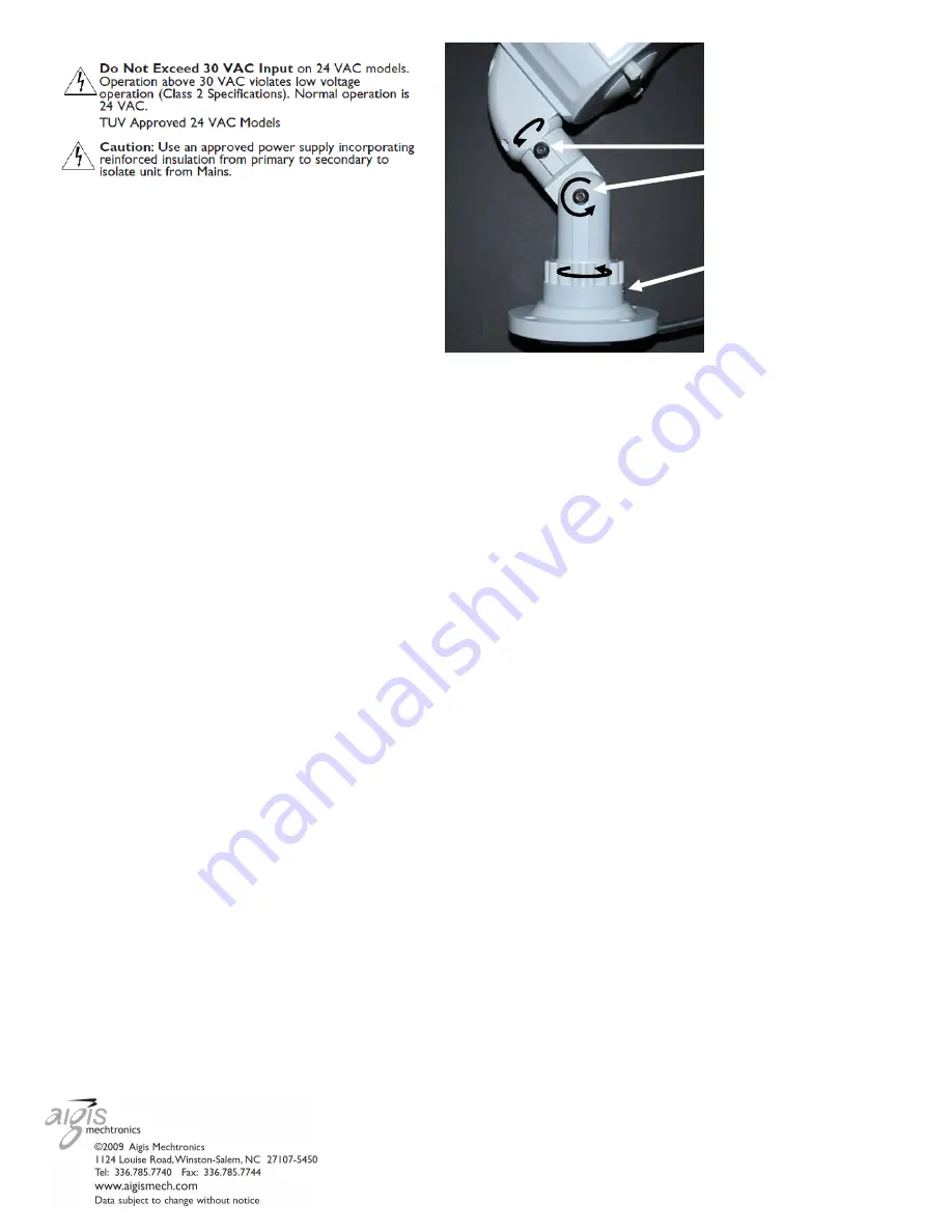
7.4. The 3-axis mounting bracket is fully adjustable to attain any viewing angle. See Figure 1 for bracket
adjustment instructions.
8. Camera / Lens Adjustment
8.1. This camera features external zoom and focus knobs. Once the desired viewing angle is attained, connect a
test monitor to the BNC connector and power the unit using 24VAC. If the knob is too tight to turn, unscrew the
screw in the center of the knob (1/4 turn at a time) until the knob can be turned. Be careful not to unscrew the
knob entirely.
8.2. Once the zoom and focus settings are in the desired range, tighten the screws to lock the knobs in place.
Set Screw (use 1/16”
Allen wrench to adjust)
Loosen to adjust viewing angle
using the 1/8” Allen wrench.
Figure 1 – Mounting Bracket Adjustment
4
100 0236 001 AIG 05/09
Printed in the U.S.A.


