AIC NESTA 120 Installation And Maintenance Manual Download Page 41

I-41

A-070336_EN • B_0821

P

roduct

 I

nstallatIon

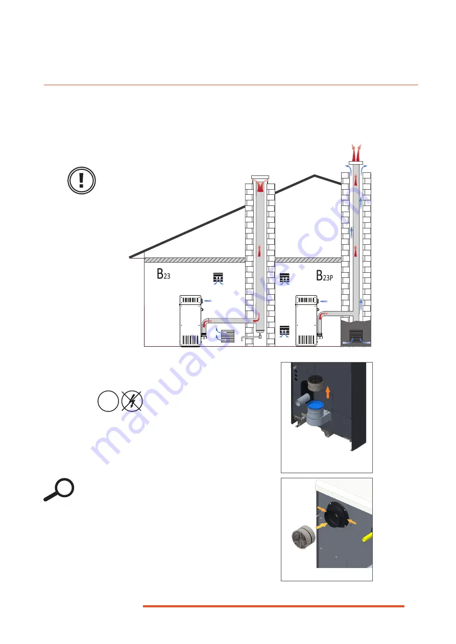
Silencer Installation in Open Chimney Sys-

tems (B)

Conditions:

Tools and material:


Cordless screwdriver, size 3.5

Procedure:

1.  Remove silencer from its storage location, in 

the flue connection.


î

Before installation, check on silenc-

er sticker that it is the correct com-

ponent for the boiler model.  If not, 

contact your AIC representative.


î

Be aware that the presence of the si-

lencer (B-type chimney connection) af-

fects the fan speed setting when carry-

ing out a gas conversion.

2.  Install silencer into air inlet connection. 
3.  Secure with 2 screws.

OFF

i

Fig. 14. Silencer removal from 

storage

Fig. 15. Silencer installation

Make sure that the ventila-

tion openings remain unob-

structed at all times. 

B (Open)

Description

B

23

Combustion air is taken directly from the boiler room, fl ue gas is discharged outside of the room 

where the appliance is installed (roof terminal).

B

23P

Same as B23, but using a positive pressure.

Summary of Contents for NESTA 120

Page 1: ...EN installation and maintenance manual FOR THE INSTALLER AND THE USER 120 160 200 250 kW FLOOR STANDING CONDENSING BOILER A 070336 B _0821 NESTA...

Page 2: ...I 35 Hydraulic Connections Cascaded boilers with External Domestic Hot Water Tank and Plate Heat Exchanger I 36 Hydraulic Connections Cascaded boilers with External Domestic Hot Water Tank and Low Lo...

Page 3: ...Boilers in a Cascade System I 67 Boiler Settings for the Installer I 70 Access Levels I 70 Commissioning Menu I 70 Menus and Settings I 70 Structure of Menus for the Installer I 70 Error Codes and Sol...

Page 4: ...17 Gas Valves Pre adjustments for Propane I 45 Fig 18 Fan Speed Adjustment Typical Screen I 46 Fig 19 Combustion Adjustment Control Panel I 47 Fig 20 Combustion Adjustment on Gas Valves I 48 Fig 21 Ac...

Page 5: ...ions provided herein The applicable regulations and standards The installer shall provide the end user with Any relevant explanation about the op eration of the appliance and the heat ing system as we...

Page 6: ...uation that can cause serious damage to equip ment and or injuries or death Indicates an important instruction which if not followed could re sult in a hazardous situation that could cause damage to e...

Page 7: ...shall not play with the appliance Any modification to the appliance and its components is strictly forbidden without the prior written consent of the manufacturer If components need to be replaced on...

Page 8: ...allation and maintenance manual before installing the boiler The boiler is pre adjusted in the factory to the gas pressure of 20mbar for gas type G20 Gas appliance category Gas type Gas appliance pres...

Page 9: ...page I 67 for more information on cas cade system possibilities Frost Protection The Nesta boilers have a built in an ti frost protec tion The pump and the burner are started as re quired when the re...

Page 10: ...ged 14 Electronic main board and cable hub for optional module connection see Optional Modules on page I 66 15 Electronic junction box 16 Control panel with LCD display 17 Burner plate temperature lim...

Page 11: ...ged 14 Electronic main board and cable hub for optional module connection see Optional Modules on page I 66 15 Electronic junction box 16 Control panel with LCD display 17 Burner plate temperature lim...

Page 12: ...nance code special mode messages and INFO lines It also allows to access the various user lev els of the controller menus 5 Chimney sweep function button This button allows to perform a measurement of...

Page 13: ...is mode is activated a black line is displayed under the symbol Reduced mode This mode operates the appliance up to the temperature setpoint defined for the reduced operation and main tains it continu...

Page 14: ...250 FS A mm 731 731 753 753 B mm 787 787 859 859 C mm 528 528 534 534 D mm 469 479 479 485 E mm 167 167 167 167 F mm 1 324 1 324 1 324 1 324 G mm 1 307 1 321 1 309 1 313 H mm 1 098 1 098 1 098 1 098...

Page 15: ...1 flue gas exhaust connection mm 130 180 combustion air inlet connection mm 125 125 condensate drain connection mm 25 25 min cross section area of air inlet mm2 12 000 12 000 Clearances Min Recommende...

Page 16: ...107 5 107 2 107 5 107 6 107 7 useful efficiency at 30 return at 30 C 108 7 108 3 108 0 108 0 seasonal efficiency 93 93 93 93 boiler type and model N 120 FS N 160 FS N 200 FS N 250 FS condensing boiler...

Page 17: ...temperature C 97 max flue gas pressure incl max wind condition Pa 200 mass flow rate of flue gases g s 6 47 9 64 12 80 9 101 max condensate volume kg h 14 4 18 6 24 0 30 0 CO emissions mg kWh 64 5 64...

Page 18: ...0 1 9 7 6 2 3 9 2 Tolerance is 0 3 15 C 1013 25 mbar dry gas Gas category Gas type Country of destination I2E S G20 BE I2H G20 AT CH CY CZ DK EE ES FI GB GR HR IE IT LT LU LV NO PT RO SE SI SK TR I2E...

Page 19: ...0 FS N 250 FS water content l 51 47 66 62 hydraulic pressure drop at T 20k mbar 80 88 101 109 minimum operating pressure bar 0 8 maximum operating pressure bar 6 maximum boiler supply temperature C 85...

Page 20: ...ppliance Do not modify or deactivate any compo nent noranysafetydeviceinthesystem Do not operate the appliance when the casing is open IF YOU SMELL GAS DO NOT Use an open flame Smoke Use electrical de...

Page 21: ...staller as required When cleaning the appliance cabinet panels do not use sol vents or aggressive abrasive cleaning agents Wipe the sur faces using a soft clean cloth water and soap i If works need to...

Page 22: ...s pushed in and is illuminated 3 Select the heating mode as required 4 Activate the DHW mode as required Follow on tasks Check the pressure of the circuit in operation It should be between 1 2 and 6 b...

Page 23: ...set it as required Error code 133 displayed Time out for flame ignition 1 Press Reset button 2 If the fault appears several times call your installer Error code 111 displayed Temperature limit switch...

Page 24: ...nob 1 to scroll through the menu until Heating circuit 1 3 is highlighted 3 Press the OK button 2 to validate the selection 4 Rotate the knob 1 to select Room comfort setpoint 5 Press the OK button 2...

Page 25: ...ess the Heating Mode Selection button 4 to go back to the home screen Date and time 1 Press the OK button 2 to access the end user menu 2 Rotate the knob 1 to scroll through the menu until Time and Da...

Page 26: ...ect the required language DE EN FR IT NL ES DA SV FI PT 5 Press the OK button 2 to save the selection 6 Press the Heating Mode Selection button 4 to go back to the home screen Unit Selection 1 Repeat...

Page 27: ...range selection 1st phase on 6 00 Adjust as required day or range selection 1st phase off 22 00 Adjust as required Identical menus for 2nd and 3rd phase adjustment Default values No Yes No Time Progra...

Page 28: ...Diagnostic code Burn ctrl phase lockout pos Service special operation Chimney sweep function Off On Off Burner output Partial load Full load Max heating load Max heating load Manual control Off On Of...

Page 29: ...ical circuit isolate the electri cal supply of the appliance through the external power cutting device fuse circuit breaker etc All connections electrical flue pipe hydraulic gas must be carried out i...

Page 30: ...bottom front panel Refer to Re moving and Installing the Access Panels on page I 31 4 Using an hex head size 5 wrench remove four screws See Fig 9 from the bottom of the boiler and the pallet Installi...

Page 31: ...the studs from their receptacles Side Panels 1 Top remove four screws Retain hardware for reinstallation 2 Bottom remove six screws Retain hardware for reinstallation Installation procedure Bottom Fr...

Page 32: ...on vessel that is appropriate for the appliance power and the system size and the increase in temperature and pressure The use of antifreeze in the pri mary circuit will lead to a reduc tion in the he...

Page 33: ...he appliance must be installed according to the manufacturer s instructions Additives can be used to keep the oxygen in solution in the water Use the additives in accordance with the in structions of...

Page 34: ...eatment Graph description Above the curves water treatment is required Below the curves fill with untreated tap water Example Boiler 120kW Installation capacity 1800l 1800l 120 kW 15 l kW From Table 1...

Page 35: ...n connection and install an optional draining valve see Fig 4 Nesta 200 250 Boiler Components Front and Rear Views on page G 11 Isolating valve Filling valve Draining valve Check valve Expansion vesse...

Page 36: ...it pump DHW circuit pump Motorised 3 way valve when needed for low temp systems Heating circuit Plate heat exchanger Drain Safety group automatic air relief valve manome ter safety valve connected to...

Page 37: ...Low Loss Header Expansion vessel Heating circuit pump DHW circuit pump Heating circuit Low loss header Drain External DHW tank Safety group automatic air relief valve manome ter safety valve connecte...

Page 38: ...ble local regulations and stand ards It must be cleaned and serviced regularly Make sure to secure the flue piping to a solid structure Exclusively use the provid ed brackets to support the flue syste...

Page 39: ...the pipe and the sleeve end stop The flue system should be fitted with an inspection opening Do not exceed the maximum length rec ommended for the product when con necting the flue pipes or the syste...

Page 40: ...is connected to a system that is approved and sold separately ex ternal supplier The air inlet flue outlet orifices may terminate in zones of different pressure Maximum allowable draught is 200 Pa Ma...

Page 41: ...ve Be aware that the presence of the si lencer B type chimney connection af fects the fan speed setting when carry ing out a gas conversion 2 Install silencer into air inlet connection 3 Secure with 2...

Page 42: ...The chimney system must be en gineered by a qualified profession al according to local standards and regulations The overall installation resistance of each boiler should not exceed 200 Pa including...

Page 43: ...equired Do not exceed the maximum gas pressure The conversion of the appliance from natural gas to G31 liquefied petroleum gas propane or the re verse can only be performed by a qualified professional...

Page 44: ...y adjustments of gas valve through shutter and offset screws of boiler settings fan speeds at ignition and at max and min out puts Conversion can therefore be carried out either on a boiler about to b...

Page 45: ...the Boiler for Gas Conversion Conditions Tools and material Wrench hex head sizes 2 4 6 Screwdriver flat head Procedure 1 Remove the top panel N 120 FS N 160 FS or left side top panel N 200 FS N 250 F...

Page 46: ...type B or C Refer to Table 1 and Table 2 on page I 44 i 9 Rotating the knob 4 adjust the ignition fan speed for the gas type boiler type and chim ney type Refer to Table 1 and Table 2 on page I 44 10...

Page 47: ...onfirm On the gas analyser check the CO2 con tents and compare the value with those in the table below Fig 19 Combustion Adjustment Control Panel 3 0 4 8 12 16 20 24 OK ESC 1 2 4 XXX 5 ON Combustion a...

Page 48: ...alue by turning the offset screw 7 in small steps to allow the value to stabilise before performing additional adjustments N 120 160 FS Rotate offset screw 7 clockwise to in crease the CO2 contents Ro...

Page 49: ...iance to allow electri cal isolation Do not touch the appliance with any wet body parts when it is supplied with electrical power Before performing any operation on the electrical circuit isolate the...

Page 50: ...ion Conditions Tools and material Wrench hex head size 4 Procedure 1 Remove center front panel see Removing and Installing the Access Panels on page I 31 2 Remove one screw 1 at the bottom of the elec...

Page 51: ...o tect and secure the cables i 1 Fig 22 Accessing the High Voltage Terminals Conditions Tools and material Wrench hex head size 4 Procedure 1 Remove two screws 1 from the panel Re tain the panel and h...

Page 52: ...N BN BU BU BN BN GNYE BU Display Unit GY Cable HUB GY GY T1A DS3 DS2 H3 QX2 QX1 QX3 2 3 4 X18 7 6 5 4 3 8 9 10 11 12 Nesta Controller N L1 NO N L1 NC L PE 230V 50Hz 5 4 3 X1 1 2 H1 1 2 H6 BX1 BX2 BX3...

Page 53: ...GND BX4 B7 RESET 15V 5V BSB Bus room unit 1 14 BSB EM H3 B2 CL CL X7a G CL CL G BSB Operator Unit X30 H7 X4 9 8 7 6 5 4 3 2 1 2 X8 X15 5 4 3 2 1 X16 1 2 3 4 UX2 UX3 1 2 3 4 5 6 7 8 H1 H4 H5 X6a X10a...

Page 54: ...sure in the water circuit check for leaks and repair as required Once the lling of the heating circuit is complete close the lling valve Check that all connections electrical ue pipe hydraulic gas hav...

Page 55: ...Date using the knob 4 validate the selection by pressing OK 3 Press the heating mode selection button 1 to exit and go back to the home screen 3 Activate the required heating mode by press ing the he...

Page 56: ...appliance permanently Inspection and maintenance tasks must be carried out by a quali ed and certi ed professional at least once a year Water owing out of the drain valve can be extremely hot Use extr...

Page 57: ...water if required X X Check the operation of the burner flame through the sight glass and that the combustion parameters CO CO2 are according to requirements See Combustion Data on page G 17 X X Chec...

Page 58: ...elect the desired heating mode if required 3 Activate the DHW mode as required 4 Allow the appliance to operate for a few min utes then bleed the air from the system Follow on tasks 1 Check there is n...

Page 59: ...6 Release two screws 3 and open the con densate trap cover 4 Retain cover and hardware for reinstallation OFF 7 Remove the cover gasket 5 Discard 8 Wipe clean the condensate level switch 7 attached to...

Page 60: ...ndi tion Discard and replace the O ring if it is dirty or cracked 8 Release four nuts 7 securing the fan and air adapter assembly 1 to the burner assembly 9 Remove the fan and air adapter assembly 1 a...

Page 61: ...nect all connectors to the electrodes burner plate limit switch gas valve and fan 9 Reconnect the air hose to the gas valve and air inlet port Follow on task s 1 Close all panels refer to Removing and...

Page 62: ...remove insulation from the upper plate Re tain for reinstallation OFF i 3 Release two screws 1 from the electrode flange 4 Remove the electrode and screws from the burner plate 3 Discard as required...

Page 63: ...es and a face mask clean with compressed air to remove residues If it is in bad condition after cleaning replace it OFF 3 Clean the combustion chamber see Check ing and Cleaning the Combustion Cham be...

Page 64: ...sing a nylon bristle brush sweep the walls of the combustion chamber 2 Using an industrial vacuum cleaner remove all deposits from the combustion chamber heating surfaces Follow on tasks 3 Install the...

Page 65: ...ons ON Fig 31 Testing the Air Pressure Switch and Flue Pressure Switch 4 FPS blow air into the hose while it is con nected to the flue pressure switch and to the measuring device 5 APS suck air from t...

Page 66: ...les Each extension supply needs to be provided with power supply and a bus connection Web Server Module Through the use of this module you can connect to an Ethernet and get remote access to the boile...

Page 67: ...h device address 1 assumes the role of the cascade master and the others are slaves The master boiler activates the required functions and shows the additional menus with the parame ters for use with...

Page 68: ...a nometer 7 Plate heat exchanger 8 Air vent 9 DHW Pump 10 DHW Storage tank 11 DHW Storage tank temperature sensor 12 Check valve 13 Water pressure sensor 14 Room unit Room thermostat 15 Mixing valve 1...

Page 69: ...rge ma nometer 7 Low loss header 8 Air vent 9 DHW Pump 10 DHW Storage tank 11 DHW Storage tank temperature sensor 12 Check valve 13 Water pressure sensor 14 Room unit Room thermostat 15 Mixing valve 1...

Page 70: ...will come up It can be exited without adjustments by pressing the ESC 3 button If the parameters are not set and saved the screen will open automatically the next time the boiler is turned on until t...

Page 71: ...tion 2nd phase off h min Eu 505 day or range selection 3rd phase on h min Eu 506 day or range selection 3rd phase off h min Eu 516 Default values No Yes No Time Pro gram 5 Eu 600 Select Mo Su Mo Su Mo...

Page 72: ...C E 744 Swi on ratio room stat C 746 Delay heat request 0 s E 750 Room influence 20 E 760 Room temp limitation 1 C E 770 Boost heating 3 C E 780 Quick setback Off To reduced setpoint To frost prot se...

Page 73: ...hangeover None Protection Reduced Comfort Automatic Protection Boiler Eu 2214 Setpoint manual control 60 C Fault Eu 6705 SW Diagnostic code Eu 6706 Burn ctrl phase lockout pos Service spe cial opera t...

Page 74: ...error Short circuit or Open circuit boiler return sensor Check connection and sensor Replace as required 46 Cascade return tempera ture sensor error Check connection and sensor Replace as required 47...

Page 75: ...ormation 109 Supervision boiler temper ature Contact AIC technical support 110 STB SLT lockout No heat removal STB interrup tion possible short circuit in the gas valve internal fuse faulty Allow devi...

Page 76: ...stuck in Check reset button 160 Fan speed threshold not reached Fan possibly defective speed threshold set wrongly Check parameters connections and component Replace as required 162 Air pressure swit...

Page 77: ...em pressure 243 Swimming pool sensor error Check connection and sensor Replace as required 260 Flow temperature 3 sensor error Check connection and sensor Replace as required 270 Temperature differenc...

Page 78: ...ad dress error Correct device address 351 Primary controller system pump address error Correct device address 352 Pressureless header ad dress error Correct device address 353 Sensor B10 missing Commo...

Page 79: ...quired 432 Function ground not con nected Check ground connection and install as required 433 Temperature primary heat exchanger too high Check the heating system external hy draulic components Mainte...

Page 80: ...nections and circuit 2 Check that pressure measuring points are closed Unburned gas smell Leak in flue gas circuit 1 Check tightness of connections 2 Check there are no obstructions in the flue system...

Page 81: ...burner Wrong chimney pressure drop Check chimney pressure drop Temperature too high compared to setpoint Boiler controller malfunction 1 Check temperature setpoint 2 Check controller operation 3 Chec...

Page 82: ...eating circuits Floor heating Radiators Other Cascade Y N Number of boilers Water Water hardness at start up mol m or mg l System volume L Additive s Antifreeze Y N Type Quantity Gas Type Heating valu...

Page 83: ...ue gas Open or closed system Dimensions of combustion air open ings if closed system cm2 Material of flue piping Diameter and length of piping sys tem mm m Chimney system engineered by Calculated pres...

Page 84: ...e controller Other controller Y N Type Optional modules installed Y N Type Optional items installed Y N Outdoor sensor Y N Type Room unit s Y N Type Others Miscellaneous The end user has received all...

Page 85: ...I 85 A 070336_EN B_0821 Additional Information for the Installer CO2 Flue gas T Remarks Name Date Signature Combustion Parameters Log Sheet...

Page 86: ...re Water Parameters Log Sheet Recommended parameters to be checked during installation and operation of the boiler Meter reading before initial filling Z m3 Date Meter reading Znew in m3 Quantity of W...

Page 87: ...I 87 A 070336_EN B_0821 Declaration of Conformity...

Page 88: ...AIC Europe B V Graafschap Hornelaan 163A NL 6001 AC Weert The Netherlands www myaic eu...

Reviews: