background image


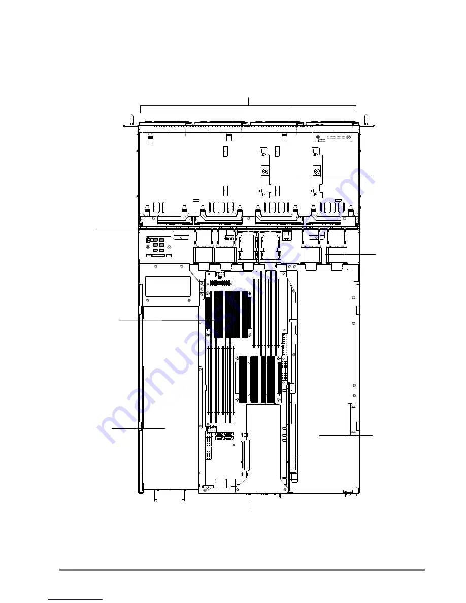
1.5 Top View of GB109-CT 


The barebone server includes the basic components shown below. 


Castor


Motherboard


Power


Supply


Expansion


Slots


System


Fans


SAS/SATA


Backplane


Hot

swap


HDD


trays


Rear


I/O


2.5”


Internal


Drive


Bracket


Summary of Contents for GB109-CT

Page 1: ...GB109 CT General Purpose Server Barebone User s Manual Document Number MAN 00102 A GB109 CT General Purpose Server Barebone User s Manual Document Number MAN 00102 A...

Page 2: ...Fans 21 2 8 Power Supply 22 2 8 1 Removing or Replacing the Power Supply Module 22 2 9 Fan Duct 22 1 Contents Contents 1 Safety Information 3 About This User s Manual 4 Chapter 1 Product Introduction...

Page 3: ...out AIC products and is not to be disclosed or used except in accordance with applicable agreements 2 Contents 2 9 1 Installing the Fan Duct 22 Chapter 3 Motherboard Settings 23 3 1 Motherboard Layout...

Page 4: ...acle Use of this type of adapter may result in risk of electric shock and or damage to this product 3 Safety Information When installing operating or performing maintenance on this equipment basic saf...

Page 5: ...Hardware Setup Motherboard Settings BIOS Configuration and Settings BMC Configuration and Settings 4 About This User s Manual This document provides a detailed description of the GB109 CT including T...

Page 6: ...Screw Kit 1 x Internal SAS to SAS Cable 2 x Internal SATA to SATA Cables 1 x 28 Rail 2 x Heatsinks 5 Chapter 1 Product Introduction 1 1 General Information GB109 CT a 1U 4bay General Purpose Barebone...

Page 7: ...P with SGPIO support System BIOS BIOS Type AMI BIOS SPI Serial Peripheral Interface FLASH Interface 6 1 2 System Specifications Dimensions with chassis ears protrusions W x D x H mm 482 6 x 711 2 x 44...

Page 8: ...ndition 0 10K feet Storage Temperature 20 60 C System Relative Humidity 5 to 95 38 C non condensing 7 BIOS Features ACPI 1 0 2 0 3 0 PXE 2 0 WOL AC loss recovery IPMI KCS interface SMBIOS 2 0 Serial c...

Page 9: ...h efficiency 650W 1 1 hot swap redundant power supplies 80 4 x RJ45 ports DB 9 serial port VGA port 8 1 3 Front View of GB109 CT 1 4 Rear View of GB109 CT LED Icon Color Behavior Controls Icon System...

Page 10: ...pansion Slots System Fans SAS SATA Backplane Hot swap HDD trays Rear I O 2 5 Internal Drive Bracket 9 1 5 Top View of GB109 CT The barebone server includes the basic components shown below Castor Moth...

Page 11: ...er from chassis 2 1 2 Removing the Fan Duct 1 Release three screws to remove the fan duct 6 32 6 32 10 Chapter 2 Hardware Setup This section demonstrates maintenance procedures in replacing a defectiv...

Page 12: ...processor hold the processor only by its edges to avoid touching the contacts Load lever Load plate 11 2 2 Central Processing Unit CPU 2 2 1 Installing the CPU 1 Press the load lever to release the lo...

Page 13: ...sed against them Please keep the socket protective cover on when processor is not installed Cutouts 12 4 Align the processor cutouts against the socket notches 5 Close the load plate load lever Press...

Page 14: ...mal paste to the bottom of heatsink and spread in an even thin layer before installing the heatsink 13 2 2 2 Installing the CPU Heatsink To install the CPU heatsink 1 Place the heatsink on top of the...

Page 15: ...1 CH0 8 DIMMs CPU0 DIMM 0 CPU1 DIMM 0 CPU0 DIMM 0 CPU1 DIMM 0 CPU0 DIMM 0 DIMM 1 CPU1 DIMM 0 DIMM 1 14 2 3 System Memory This server board supports up to twelve DDR3 800 1066 1333 Registered ECC SDRAM...

Page 16: ...press down until it snaps into place Note DIMM notch and socket bump must align as shown DIMM notch 15 CH2 CH1 CH0 10 DIMMs CPU0 DIMM 0 CPU1 DIMM 0 CPU0 DIMM 0 DIMM 1 CPU1 DIMM 0 DIMM 1 CPU0 DIMM 0 DI...

Page 17: ...when its front edge aligns with the bay edge 5 Repeat Steps 1 through 4 to install the rest of HDDs 16 2 4 Drive Bays 2 4 1 Installing or Replacing 3 5 Hot swap SAS SATA HDD 1 Release a drive tray by...

Page 18: ...HDD into the pins 3 Tighten the thumb screw 4 Repeat Steps 1 through 4 to install the rest of HDDs 17 2 4 2 Installing or Replacing 2 5 Internal SAS SATA HDD 1 Release the thumb screw Pull the bracke...

Page 19: ...Riser for Castor RISER CARD DIAGRAM M H 4 M H 3 M H 2 M H 1 J2 A 1 A 11 A 12 A 49 Slot Bandwidth X8 18 2 5 Riser Card 1 RISER CARD PN PSG CODE DESCRIPTION PSG RC AQ1U 20 111 PE1U04 1U Gold finger PCIe...

Page 20: ...with the two screws and card retainer to fix the expansion card Card retainer Card retainer bracket 19 2 6 Expansion Slot 2 6 1 Install an External Expansion Card to the Riser Card 1 Remove two screws...

Page 21: ...holder Secure it with one screw 3 Secure the bracket back with the screws to fix the expansion card 20 2 6 2 Install an External Expansion Card to the Riser Card Low profile 1 Remove two screws on top...

Page 22: ...ely connecting the top hooks Fan cable Caution shut down the system before removing the system fans 21 2 7 System Fans 2 7 1 Removing or Replacing the System Fans 1 Disconnect the fan cable 2 Remove t...

Page 23: ...1 Installing the Fan Duct 1 Put the fan duct on the fan bar and secure with three screws 6 32 6 32 22 2 8 Power Supply 2 8 1 Removing or Replacing the Power Supply Module 1 Hold the PSU lever and fir...

Page 24: ...HEADER J5 1 LAN LED J19 4 KB MS J7 2 DEBUG PORT J8 5 LCM CONN J19 3 FRONT PANEL J15 6 BUZZER 5V J18 23 Chapter 3 Motherboard Settings This section describes the jumper settings of AIC s Castor PSG M C...

Page 25: ...ET OFF NORMAL J29 CLEAR CMOS 1 3 1 2 NORMAL 2 3 CLEAR OPEN INVALID SW1 PCIe Strapping Configuration 24 3 2 1 Jumpers J14 VGA DISABLE 1 2 1 2 DISABLE OFF ENABLE J21 AST ARM 1 2 1 2 DISABLE OFF ENABLE J...

Page 26: ...5 MS_DATA 6 GND J9 LCM CONN 1 POWER_BTN 2 RESET_BTN 3 TX 4 RX 5 GND J18 BUZZER 5V 1 BUZZER 2 BUZZER 25 3 2 2 Internal Connectors JP1 BMC DEBUG 1 3 1 Tx 2 Rx 3 GND J6 UART COM2 9 NC 10 GND 7 RI 8 DTR 5...

Page 27: ...AN8_TACH 3 FAN1_TACH 4 PWM1 5 FAN2_TACH 6 PWM2 7 FAN3_TACH 8 PWM3 9 FAN4_TACH 10 PWM4 11 GND 12 GND 26 3 2 3Internal Connectors continue J46 BMC GPIO 5 BMC_GPIOE6 6 BMC_GPIOB2 4 BMC_GPIOB7 3 BMC_GPIOE...

Page 28: ...GND 13 SYS FLT LED 14 FP NMI BTN 15 SYS FLT LED 16 GND 17 SB SMB DATA 18 5VSB 19 SB SMB CLK 20 GND 27 3 2 4 Internal LEDs J19 LAN LED LED ON LAN LINK LED BLINK ACTIVE 1 GbE1 LED 2 GbE1 LED 3 GbE2 LED...

Page 29: ...end in an 0 Caution When Quiet Boot IS enabled OEM LOGO WILL BE displayed INSTEAD OF POST MESSAGES 28 Chapter 4 BIOS Configuration and Settings 4 1 BIOS Setting 1 Press DEL to run the setup procedure...

Page 30: ...the BIOS Version 4 Load Optimal Default setting 5 Save the setting and exit the BIOS setup utility 29 3 Identify the BIOS Version 4 Load Optimal Default setting 5 Save the setting and exit the BIOS s...

Page 31: ...tem while the BIOS is updating Caution The system will reboot after exiting the BIOS update Utility 30 4 2 Updating BIOS 1 AFUDOS is a BIOS update utility with command line interface that works in DOS...

Page 32: ...se the BIOS setup 1 BIOS SETUP Advance IPMI configuration Set LAN configuration BMC management port 31 Chapter 5 BMC Configuration and Settings Insert BMC IP LAN into the BMC LAN port There are two me...

Page 33: ...IP address Set IP static Note type 1 for selecting static IP mode or type 2 for selecting DHCP mode 32 2 Input IP address Set IP static Note type 1 for selecting static IP mode or type 2 for selecting...

Page 34: ...33 3 Input subnet mask address 33 3 Input subnet mask address...

Page 35: ...tting 3 Input IP address Note type 1 for selecting static IP mode or type 2 for selecting DHCP mode 34 5 2 Method 2 Use a Dos tool Syscheck 1 Type sc lanset 2 Modify IP setting 3 Input IP address Note...

Page 36: ...use 5 Finish BMC IP configuration Note Type sc exe langet command to obtain BMC IP and MAC address 35 4 Input submask address Below IP address is an example using a default IP setting User is allowed...

Page 37: ...an be changed after login Note This feature works with JAVA 6 runtime installed console environment 36 5 3 Connect to BMC Below IP address is an example using default IP setting User is allowed to cha...

Page 38: ...Sensor Readings 5 Configuration Please refer to AIC BMC User Guide for more information on AIC BMC 37 3 Information of ASTER firmware 4 Server Health Sensor Readings 5 Configuration Please refer to A...

Page 39: ...de to absolute For Linux OS environment set mode to relative 6 Remote Control Environmental setting 38 Mouse Mode setting For Windows OS environment set mode to absolute For Linux OS environment set m...

Page 40: ...CORD 5 SECONDS AND THEN PLUG AC POWER CORD TO RESET BMC THEN UPDATED NEW FUNCTION CAN WORK PROPERLY 39 Press ALT M for local and remote OS mouse control switching 5 4 Updating BMC Firmware 1 Boot to t...

Page 41: ...CORD 5 SECONDS AND THEN PLUG AC POWER CORD TO RESET BMC THEN UPDATED NEW FUNCTION CAN WORK PROPERLY 40 5 5 Updating BMC Configuration 1 Boot to DOS MS DOS or Free DOS is workable 2 Enter BMC config fi...

Page 42: ...Tel 31 30 6386789 Fax 31 30 6360638 Email Technical Support support aicipc com Http www aicipc com 41 Chapter 6 Technical Support TAIWAN Tel 886 3 313 8386 Fax 886 3 313 8377 Email Technical Support...

Page 43: ...42 Note 42 Note...

Reviews: